r-engine-developers Mailing List for Sony Vaio R-Engine MPEG2 Linux Driver
Status: Planning
Brought to you by:
dscoular
You can subscribe to this list here.
| 2003 |
Jan
|
Feb
|
Mar
|
Apr
|
May
|
Jun
|
Jul
(2) |
Aug
|
Sep
|
Oct
|
Nov
|
Dec
|
|---|---|---|---|---|---|---|---|---|---|---|---|---|
| 2005 |
Jan
|
Feb
|
Mar
|
Apr
|
May
(1) |
Jun
(1) |
Jul
|
Aug
(7) |
Sep
(5) |
Oct
|
Nov
|
Dec
(1) |
| 2006 |
Jan
|
Feb
(1) |
Mar
|
Apr
|
May
|
Jun
|
Jul
|
Aug
|
Sep
|
Oct
|
Nov
|
Dec
|
| 2007 |
Jan
|
Feb
|
Mar
|
Apr
|
May
(1) |
Jun
|
Jul
|
Aug
|
Sep
|
Oct
|
Nov
|
Dec
|
|
From: Doug S. <dsc...@ci...> - 2007-05-23 01:41:59
|
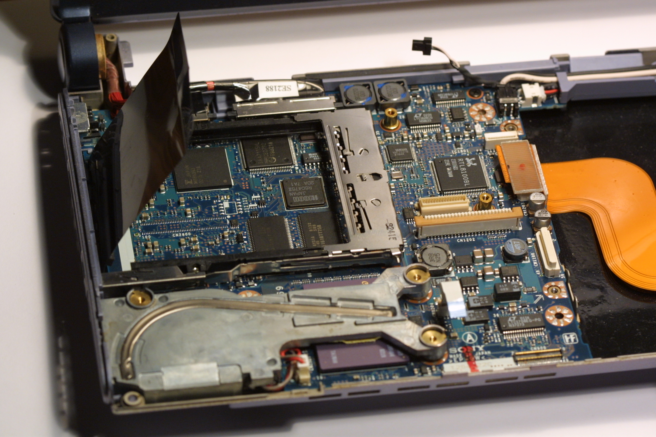
Hi Cedric, Did you ever make any progress on the VAIO SAA7115 ? There seems to be a rekindled interest in helping people develop linux drivers... http://www.kroah.com/log/linux/free_drivers.html I have no understanding of low level development but try to occasionally keep the r-engine.sf.net web site alive. Cheers, Doug Cedric Cellier wrote: > I've just opened up my Vaio. > > This is really easy : from the 5 screws that are under the laptop, > remove the central one, this is the one that grasp the keyboard. Then, > with a very small screwdriver, unclip the keyboard (the two clips are at > the bottom left and bottom right of the keyboard). Then you can lift it > slowly. A flat connector have to be unplugged from the laptop so that > you can rotate the keyboard upward right to the screen. Then you can > unclip the metal cover of the pcmcia hole, then unstuck the plastic > protection under the pcmcia hole to reveal the mb86393 and the saa7115. > > Thank you Peter ! :-) > > Then, you need good eyes to count the pins... > > I will try to take pictures on my own tomorrow (my girlfriend owns a > good camera) so that it will be easier to follow the circuitry, > hopefully. I've done a rough sketch of the SAA7115 because I wanted to > know if the RTCO was soldered to a resistor or not (giving the I2C w/r > register), and it seams that it's the case, so the registers should be > 40h and 41h instead of the default 42h/43h. Other people should be able > to confirm this on the pictures. > > As for the GPIO, I think I have spotted the SCL/SDA lines on the SAA7115 > side. But one can barely follow them, for the 2 lines quickly goes under > cover and because the 8 GPIO pins are soldered under the MB86393, in the > center of it (pins #48, 51, 56, 132, 134, 135, 204 and 206). Perhaps we > can see them on the other side of the board, but one must remove the > board completely to find out ... > > Stay tuned people ! :-) > > > ------------------------------------------------------- > SF.Net email is sponsored by: > Tame your development challenges with Apache's Geronimo App Server. > Download > it for free - -and be entered to win a 42" plasma tv or your very own > Sony(tm)PSP. Click here to play: http://sourceforge.net/geronimo.php > _______________________________________________ > R-engine-developers mailing list > R-e...@li... > https://lists.sourceforge.net/lists/listinfo/r-engine-developers -- "The big print giveth and the small print taketh away" |
|
From: Doug S. <dsc...@ci...> - 2006-02-08 01:43:24
|
Hi All,
    Just wanted to mention that I've put up some
    great exploded parts diagrams on the r-engine
    web page.

    Check them out at:

http://r-engine.sf.net/

    Cheers,

    Doug
|
|
From: Doug S. <dsc...@ci...> - 2005-12-17 03:03:55
|
Hi All, I posted this up on the r-engine site: http://r-engine.sourceforge.net/dismantle.html Enjoy, Doug |
|
From: Cedric C. <ri...@ha...> - 2005-09-22 00:32:43
|
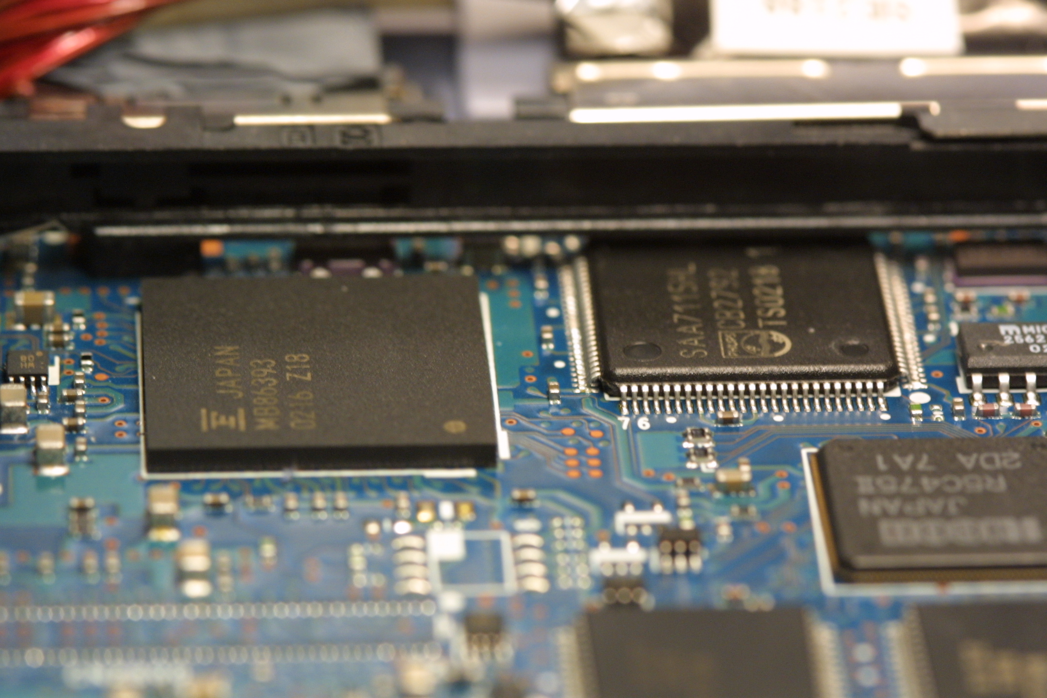
I've just opened up my Vaio. This is really easy : from the 5 screws that are under the laptop, remove the central one, this is the one that grasp the keyboard. Then, with a very small screwdriver, unclip the keyboard (the two clips are at the bottom left and bottom right of the keyboard). Then you can lift it slowly. A flat connector have to be unplugged from the laptop so that you can rotate the keyboard upward right to the screen. Then you can unclip the metal cover of the pcmcia hole, then unstuck the plastic protection under the pcmcia hole to reveal the mb86393 and the saa7115. Thank you Peter ! :-) Then, you need good eyes to count the pins... I will try to take pictures on my own tomorrow (my girlfriend owns a good camera) so that it will be easier to follow the circuitry, hopefully. I've done a rough sketch of the SAA7115 because I wanted to know if the RTCO was soldered to a resistor or not (giving the I2C w/r register), and it seams that it's the case, so the registers should be 40h and 41h instead of the default 42h/43h. Other people should be able to confirm this on the pictures. As for the GPIO, I think I have spotted the SCL/SDA lines on the SAA7115 side. But one can barely follow them, for the 2 lines quickly goes under cover and because the 8 GPIO pins are soldered under the MB86393, in the center of it (pins #48, 51, 56, 132, 134, 135, 204 and 206). Perhaps we can see them on the other side of the board, but one must remove the board completely to find out ... Stay tuned people ! :-) |
|
From: Cedric C. <ri...@ha...> - 2005-09-21 23:29:04
|
Please have a look at pics here : http://silicon-verl.de/home/flo/software/c1mhp/pics/index.html especially : http://silicon-verl.de/home/flo/software/c1mhp/pics/2003042522445200.jpg and http://silicon-verl.de/home/flo/software/c1mhp/pics/2003042522434900.jpg Where we can see our old friend the MB86393, with it's friend, which appears to be, quite surprisingly, a SAA7115 instead of a SAA7114. Specs of this new thing are easy to find on the web. Unfortunately, I2C R/W registers are the same, so nothing's really new... |
|
From: Peter M. <pe...@mc...> - 2005-09-08 22:21:51
|
I'm sorry I no longer have my C1 viao so I'm going to find it difficult to help out. Un fortunately I didn't manage to pull appart the machine and check the exact circuit for the GPIO pins before it went... However I'd suggest someone do that, it's not htat hard if you know anything about electronics. Cedric Cellier wrote: > I received dumps of bank 0 from Emmanuel Fleury, a c1msx user who > conserved a window (his page at http://www.cs.auc.dk/~fleury/bug_cms/ > may interrest you). > > The dumps are attached. > > I also attach my bank 0. > > mb86393_ioscan.windows_off is when the camera is inactive. > mb86393_ioscan.windows_on is when the camera is active > mb86393_ioscan is mine. > > You will see than when active there is only one bit that is toggled in > the control register (documented somewhere ?). > > Comparing with mine, there are not many changes apart from mapped > address ranges. > > The GPIO register invariably equal zero, which is the bad news. > > Does somebody know of a tool under windows that can monitor every > access to these port (feasable in protected mode) so that we can see > what's done by the driver when initializing ? > >------------------------------------------------------------------------ > >00 CF 10 11 20 07 00 90 02 00 00 80 04 00 40 00 00 >10 01 FC 00 00 00 00 C0 FB 00 00 00 00 00 00 00 00 >20 00 00 00 00 00 00 00 00 00 00 00 00 4D 10 EC 80 >30 00 00 00 00 40 00 00 00 00 00 00 00 09 01 00 00 >40 01 00 02 00 00 00 00 00 00 00 00 00 00 00 00 00 >50 00 00 00 00 4D 10 EC 80 00 00 00 00 00 00 00 00 >60 00 00 00 00 00 00 00 00 00 00 00 00 00 00 00 00 >70 00 00 00 00 00 00 00 00 00 00 00 00 00 00 00 00 >80 00 00 00 00 00 00 00 00 00 00 00 00 00 00 00 00 >90 00 00 00 00 00 00 00 00 00 00 00 00 00 00 00 00 >A0 00 00 00 00 00 00 00 00 00 00 00 00 00 00 00 00 >B0 00 00 00 00 00 00 00 00 00 00 00 00 00 00 00 00 >C0 00 00 00 00 00 00 00 00 00 00 00 00 00 00 00 00 >D0 00 00 00 00 00 00 00 00 00 00 00 00 00 00 00 00 >E0 00 00 00 00 00 00 00 00 00 00 00 00 00 00 00 00 >F0 00 00 00 00 00 00 00 00 00 00 00 00 00 00 00 00 > > >------------------------------------------------------------------------ > >00 CF 10 11 20 07 00 90 0A 00 00 80 04 00 40 00 00 >10 01 FC 00 00 00 00 C0 FB 00 00 00 00 00 00 00 00 >20 00 00 00 00 00 00 00 00 00 00 00 00 4D 10 EC 80 >30 00 00 00 00 40 00 00 00 00 00 00 00 09 01 00 00 >40 01 00 02 00 00 00 00 00 00 00 00 00 00 00 00 00 >50 00 00 00 00 4D 10 EC 80 00 00 00 00 00 00 00 00 >60 00 00 00 00 00 00 00 00 00 00 00 00 00 00 00 00 >70 00 00 00 00 00 00 00 00 00 00 00 00 00 00 00 00 >80 00 00 00 00 00 00 00 00 00 00 00 00 00 00 00 00 >90 00 00 00 00 00 00 00 00 00 00 00 00 00 00 00 00 >A0 00 00 00 00 00 00 00 00 00 00 00 00 00 00 00 00 >B0 00 00 00 00 00 00 00 00 00 00 00 00 00 00 00 00 >C0 00 00 00 00 00 00 00 00 00 00 00 00 00 00 00 00 >D0 00 00 00 00 00 00 00 00 00 00 00 00 00 00 00 00 >E0 00 00 00 00 00 00 00 00 00 00 00 00 00 00 00 00 >F0 00 00 00 00 00 00 00 00 00 00 00 00 00 00 00 00 > > >------------------------------------------------------------------------ > >00 CF 10 11 20 07 00 90 0A 00 00 80 04 00 40 00 00 >10 01 20 00 00 00 00 20 E8 00 00 00 00 00 00 00 00 >20 00 00 00 00 00 00 00 00 00 00 00 00 4D 10 EC 80 >30 00 00 00 00 40 00 00 00 00 00 00 00 FF 01 00 00 >40 01 00 02 00 00 00 00 00 00 00 00 00 00 00 00 00 >50 00 00 00 00 4D 10 EC 80 00 00 00 00 00 00 00 00 >60 00 00 00 00 00 00 00 00 00 00 00 00 00 00 00 00 >70 00 00 00 00 00 00 00 00 00 00 00 00 00 00 00 00 >80 00 00 00 00 00 00 00 00 00 00 00 00 00 00 00 00 >90 00 00 00 00 00 00 00 00 00 00 00 00 00 00 00 00 >A0 00 00 00 00 00 00 00 00 00 00 00 00 00 00 00 00 >B0 00 00 00 00 00 00 00 00 00 00 00 00 00 00 00 00 >C0 00 00 00 00 00 00 00 00 00 00 00 00 00 00 00 00 >D0 00 00 00 00 00 00 00 00 00 00 00 00 00 00 00 00 >E0 00 00 00 00 00 00 00 00 00 00 00 00 00 00 00 00 >F0 00 00 00 00 00 00 00 00 00 00 00 00 00 00 00 00 > > > |
|
From: Cedric C. <ri...@ha...> - 2005-09-08 11:01:41
|
I received dumps of bank 0 from Emmanuel Fleury, a c1msx user who conserved a window (his page at http://www.cs.auc.dk/~fleury/bug_cms/ may interrest you). The dumps are attached. I also attach my bank 0. mb86393_ioscan.windows_off is when the camera is inactive. mb86393_ioscan.windows_on is when the camera is active mb86393_ioscan is mine. You will see than when active there is only one bit that is toggled in the control register (documented somewhere ?). Comparing with mine, there are not many changes apart from mapped address ranges. The GPIO register invariably equal zero, which is the bad news. Does somebody know of a tool under windows that can monitor every access to these port (feasable in protected mode) so that we can see what's done by the driver when initializing ? |
|
From: Cedric C. <ri...@ha...> - 2005-09-01 05:08:12
|
Hi list ! I am still stuck in guessing the GPIO pins. I can get some acks with bit 6 but this bit 'naturally' reads sometimes as 0 or 1 so I think this is the output of some other chip and have nothing to do with I2C, thus explaining why I can't read anything back from the SAA7114. I tried again any combination without success. The problem is the undocumented 'CF' black magic value I already speak about : this gives too many other combinations for a brute force approach, so we need another clues. So, I think we must try to write for anyone who own a C1MSX and ask for a PCI dump (also on the r-engine web-site). I've already done so. _AND_, we must ask to the Fujitsu person who contributed with the former driver what's the purpose of the 'CF' at the end of mb86393 reset. I can do it, but I need his email (a native English speaker or the one who was sent the code (Peter?) would be best, though). |
|
From: Peter M. <pe...@mc...> - 2005-08-19 00:15:47
|
Perhaps I should open up my vaio again and trace the tracks. Yep I'll do that this weekend and let you know what pins do what. On Fri, 2005-08-19 at 09:55 +1000, Peter McNeil wrote: > Two nights is nothing to get frustrated over! You're doing a fine > Stirling job! The problem here is that there are 256! or 32! possible > combinations for which GPIO pins do what. They are called General > Purpose because hardware designers are free to use any pin for anything > and quite often they select a pin because it makes the PCB layout easier > not be cause it makes logical pin sense. > > Cheers, > Peter. > > On Wed, 2005-08-17 at 23:23 +0200, Cedric Cellier wrote: > > Hello the list ! > > > > After 2 nights playing with the GPIO I am disapointed now. > > First, When you set all pins to inputs and read GPIOREAD, you got > > '0xBB'. That is all ones but 2 bits. Ive read on V4Lwiki, and it seams > > reasonnable, that the 1 bits are good candidates for outputs. > > > > I then tryed all combinations involving thoses 6 bits for SDA and SCL, > > trying to address chip address 0x42 (more probable address of a SAA7114, > > considering the SAA7113 was addressed on it's default address too). > > > > None of these combinations give me an ACK after the address was written. > > > > So, I reversed my reasoning and try bits 0x4 and 0x40 alone for SDA and > > SCL. This, neither, does not give ACK... except if you clear the bit 6 > > in what I call the 'Magick 0xC8FFFFCF', that is the 'end of reset' in > > the mb86393_reset function that's called first. > > > > I don't know where the 'CF' goes, but as its related to the GPIO I > > played with it a bit. The only thing I am certain of, is that if you use > > 0x40 for SDA and if you clear bit 0xb0 of this 0xc8ffffcf, then you will > > have all the ack you want when reading the sda (?) line. > > > > After two nights, this result is a bit frustrating. :-( > > > > > > > > ------------------------------------------------------- > > SF.Net email is Sponsored by the Better Software Conference & EXPO > > September 19-22, 2005 * San Francisco, CA * Development Lifecycle Practices > > Agile & Plan-Driven Development * Managing Projects & Teams * Testing & QA > > Security * Process Improvement & Measurement * http://www.sqe.com/bsce5sf > > _______________________________________________ > > R-engine-developers mailing list > > R-e...@li... > > https://lists.sourceforge.net/lists/listinfo/r-engine-developers -- Peter McNeil http://www.mcneils.net |
|
From: Peter M. <pe...@mc...> - 2005-08-18 23:56:22
|
Two nights is nothing to get frustrated over! You're doing a fine Stirling job! The problem here is that there are 256! or 32! possible combinations for which GPIO pins do what. They are called General Purpose because hardware designers are free to use any pin for anything and quite often they select a pin because it makes the PCB layout easier not be cause it makes logical pin sense. Cheers, Peter. On Wed, 2005-08-17 at 23:23 +0200, Cedric Cellier wrote: > Hello the list ! > > After 2 nights playing with the GPIO I am disapointed now. > First, When you set all pins to inputs and read GPIOREAD, you got > '0xBB'. That is all ones but 2 bits. Ive read on V4Lwiki, and it seams > reasonnable, that the 1 bits are good candidates for outputs. > > I then tryed all combinations involving thoses 6 bits for SDA and SCL, > trying to address chip address 0x42 (more probable address of a SAA7114, > considering the SAA7113 was addressed on it's default address too). > > None of these combinations give me an ACK after the address was written. > > So, I reversed my reasoning and try bits 0x4 and 0x40 alone for SDA and > SCL. This, neither, does not give ACK... except if you clear the bit 6 > in what I call the 'Magick 0xC8FFFFCF', that is the 'end of reset' in > the mb86393_reset function that's called first. > > I don't know where the 'CF' goes, but as its related to the GPIO I > played with it a bit. The only thing I am certain of, is that if you use > 0x40 for SDA and if you clear bit 0xb0 of this 0xc8ffffcf, then you will > have all the ack you want when reading the sda (?) line. > > After two nights, this result is a bit frustrating. :-( > > > > ------------------------------------------------------- > SF.Net email is Sponsored by the Better Software Conference & EXPO > September 19-22, 2005 * San Francisco, CA * Development Lifecycle Practices > Agile & Plan-Driven Development * Managing Projects & Teams * Testing & QA > Security * Process Improvement & Measurement * http://www.sqe.com/bsce5sf > _______________________________________________ > R-engine-developers mailing list > R-e...@li... > https://lists.sourceforge.net/lists/listinfo/r-engine-developers -- Peter McNeil http://www.mcneils.net |
|
From: Cedric C. <ri...@ha...> - 2005-08-18 20:45:43
|
Hello the list ! After 2 nights playing with the GPIO I am disapointed now. First, When you set all pins to inputs and read GPIOREAD, you got '0xBB'. That is all ones but 2 bits. Ive read on V4Lwiki, and it seams reasonnable, that the 1 bits are good candidates for outputs. I then tryed all combinations involving thoses 6 bits for SDA and SCL, trying to address chip address 0x42 (more probable address of a SAA7114, considering the SAA7113 was addressed on it's default address too). None of these combinations give me an ACK after the address was written. So, I reversed my reasoning and try bits 0x4 and 0x40 alone for SDA and SCL. This, neither, does not give ACK... except if you clear the bit 6 in what I call the 'Magick 0xC8FFFFCF', that is the 'end of reset' in the mb86393_reset function that's called first. I don't know where the 'CF' goes, but as its related to the GPIO I played with it a bit. The only thing I am certain of, is that if you use 0x40 for SDA and if you clear bit 0xb0 of this 0xc8ffffcf, then you will have all the ack you want when reading the sda (?) line. After two nights, this result is a bit frustrating. :-( |
|
From: Peter M. <pe...@mc...> - 2005-08-14 11:01:33
|
On Sat, 2005-08-13 at 13:20 +0200, Cedric Cellier wrote:
...
> So, just to be sure I understand what we have : The camera send its flow
> to a Phillips SAA7114 wich then send it to the Fujitsu mb86393, both
> circuit beeing given the name 'r-engine' by sony. The mb86393 is a PCI
> device and the code a driver of another engine ('Triumph' driver) was
> given by Fujitsu (considering japanese comments and documentation). The
> mb86393 and the saa7114 communicates via i2c. In the driver given by
> Fujitsu, the mb86393 was used with the SAA7113 instead, wich is a
> similar but simplier chip. We do not care because we know everything
> about the saa7114 thanx to previous work in media/video.
>
> Am I right ?

Pretty much, the i2c is driven via the gpio on the mb86393.

>
> If so, can I ask you a question : how do we know for the saa7114 ? The
> information comes from sony/fujitsu, or is it just a guess based on chip
> recognition ? I ask because I tried to read some of its registers
> without success.

No guess. I opened up my viao and had a look ;-)

>
> Then, if it turns out to be a sa7114, why not reusing fully the sa7114.c
> by coding the mb86393 driver as a pci_device *AND* as a i2c_adapter ?
> Maybe I'm just too unfamiliar with the linux internal designs...

Yep that would work, only point there would be having to write an i2c
driver for the 86393. The thing we don't know is which GPIO bits are
used for what signals on the circuit since they're "programmable".

That may take some sniffing the control signals under the windows
driver. Unfortunately I can't get windows reloaded on my viao at the
moment as I don't have a Sony cdrom drive.

Cheers,
Peter.

>
>
> -------------------------------------------------------
> SF.Net email is Sponsored by the Better Software Conference & EXPO
> September 19-22, 2005 * San Francisco, CA * Development Lifecycle Practices
> Agile & Plan-Driven Development * Managing Projects & Teams * Testing & QA
> Security * Process Improvement & Measurement * http://www.sqe.com/bsce5sf
> _______________________________________________
> R-engine-developers mailing list
> R-e...@li...
> https://lists.sourceforge.net/lists/listinfo/r-engine-developers
--
Peter McNeil
http://www.mcneils.net
|
|
From: Cedric C. <ri...@ha...> - 2005-08-13 20:52:53
|
Dear list, My first intentions were to skip the saa7114 completely to proceed with the mb86393. But then the first command I tried failed because, as I figured out by dumping it, the whole 1Mo of memory mapped registers are undef (that is, they all read as 0xfffffffff). So, I suppose the SAA7114 initialization must be done before accessing this memory. I thus tried to fix the SA7713 part, mainly by trying other read/write addresses : the specs says its either 40h/41h or 42h/43h. Sadly, whatever the address, I cannot write anything into the i2c bus. In fact, I cannot even write the write address : The first wait for acknowledge fails. I do not know if it's the supposed SA7714 that do not answer because he didn't get the written values, or because he is not supposed to, or if its the whole I2C bus that's not handled the same way by the mb86393 when he is attached a SA7114. I also dumped the 256bytes controller io region, and it looks like there is actually "something" at io address GPIOREG, but perhaps the procedure to write to and read from the I2C bus have changed ? At this point, I really would appreciate a datasheet of the mb86393. Any chance that we get one from Fujitsu ? |
|
From: Cedric C. <ri...@ha...> - 2005-08-13 11:20:28
|
Hi !

I just get a second hand pcg-c1msx some days ago, and I'm willing to
have the motion-eye working (not that I really need it, but as a coder
it's challenging).

I tried your code and play a little with it. I mostly get the same
results than you (SAA7113 Fail, mb86393 recognized).

So, just to be sure I understand what we have : The camera send its flow
to a Phillips SAA7114 wich then send it to the Fujitsu mb86393, both
circuit beeing given the name 'r-engine' by sony. The mb86393 is a PCI
device and the code a driver of another engine ('Triumph' driver) was
given by Fujitsu (considering japanese comments and documentation). The
mb86393 and the saa7114 communicates via i2c. In the driver given by
Fujitsu, the mb86393 was used with the SAA7113 instead, wich is a
similar but simplier chip. We do not care because we know everything
about the saa7114 thanx to previous work in media/video.

Am I right ?

If so, can I ask you a question : how do we know for the saa7114 ? The
information comes from sony/fujitsu, or is it just a guess based on chip
recognition ? I ask because I tried to read some of its registers
without success.

Then, if it turns out to be a sa7114, why not reusing fully the sa7114.c
by coding the mb86393 driver as a pci_device *AND* as a i2c_adapter ?
Maybe I'm just too unfamiliar with the linux internal designs...
|
|
From: Doug S. <dsc...@ci...> - 2005-06-22 02:24:57
|
Hi Peter,
    Hopefully others will start picking up on the fact that you've
    placed an initial stab at driver code up on CVS at r-engine.sf.net.
    I'm Cc'ing this to the r-engine-developers list to see if it sparks
    any interest.

Peter McNeil wrote:

>On Tue, 2005-06-21 at 21:38, Doug Scoular wrote:
>
>
> Leave the DMA bit out altogether just insmod mb86393 then you'll just
>
>get an error in dmesg about no saa7113.
>
>
>
    Okay, I've got the same result now, so we are on the same
    page I guess.

    A while back you said:

 > >OK Just pulled appart my PCG-C1MT to see what the video input processor
 > >was as this is important for the driver. Looks like they use the
 > >SAA7114H from philips
 > >(http://www.semiconductors.philips.com/pip/SAA7114H.html) which is very
 > >similar to the Triumph driver code we have, cool, looks like the
triumph
 > >driver might work with a couple of small tweaks.

    Does that mean we should be initialising the SAA7114H rather
    than attempting to send initialisations for an SAA7113 to an
    SAA7114H... or are both present ?

http://www.semiconductors.philips.com/acrobat_download/datasheets/SAA7114_2.pdf
http://www.gctglobal.com/Products/Set_Top_Box/STB6286N/SAA7113H_1.pdf

    Looking at the intialisation... they do seem to differ, for example
    the mb86393 code is setting 0x0e to 0x09, that's setting
    "Chrominance Control" to 0x09 but on from looking at the current
    SAA7114H driver in drivers/media/video/saa7114.c it appears that
    it has the following settings. Which looks to my ignorant eye like
    it initialises 0x0e to 0x84:

        0x0e, 0x84,      /* 0e - CDTO, CSTD2 to 0, DCVF, FCTC,
                                 * CCOMB; depends from video standard */

    Where the video standard settings are:

       0x89 = NTSC M
       0x81 = PAL B, D, G, H and I
       0xD0 = SECAM

    I've no idea what 0x84 is, perhaps plain ol NTSC... I also
    think I see the code set it to 0x85 in saa7114.c so now I'm
    really confused. I think I'm missing something fundamental
    about low-level hardware programming.

    Anyway, just thought I'd give you my, probably useless 2
    cents.

    Cheers,

    Doug
|
|
From: Robert W. <bo...@bo...> - 2005-05-23 04:39:20
|
Dear list, Is this project related to the Sony Corp. VCC-U01 Visual Communication Camera? There are several references out there to a connection between this project and the motion-eye camera on the Sony TR1-3 series of laptops. Best regards, Bob -- Dr. Robert Williams Department of Biomedical Informatics Uniformed Services University 301-295-3568 |
|
From: Doug S. <dsc...@ci...> - 2003-07-07 00:08:39
|
Hi Felix,
    I made the r-engine list a closed list that doesn't get archived
    in case we started talking about things that broke the Fujitsu
    NDA.

    An unfortunate side-effect of this is that people have to explicitly
    join this list rather than browse past archives.

    I'm copying this to the other three members of the developer
    group in case they would like to join this closed list. Maybe
    it was a mistake to make it a closed list... dunno.

    BTW, I've been in touch with Miguel Estevez (who is very
    busy just now) and he says he'll be sending me some more
    info on the chip since the NDA docs don't seem to cover
    how to send the serial command protocol to the chip or
    how to read the images. He's also stopped giving out the
    NDA docs as he was getting overwhelmed with the
    requests... he says he'll come up with some other, better
    mechanism.

    I also sent an email to the newly formed CE Linux Forum:

    http://www.celinuxforum.org

    Which is a new group set up by Sony and others to promote
    linux on consumer electronics devices. I got a response from
    their executive director saying that he will do his best to get
    us some contacts within Sony.

    I'll post when I have any updates.

    P.S. please let me know if you think it's a bad idea to have
    a closed list. Also, anyone requesting membership should
    have signed the NDA unless we decide to open the list.

    Cheers...
    Doug Scoular
    UNIX Systems Architect
|
|
From: Felix G. <fe...@ba...> - 2003-07-05 22:58:51
|
just testing. greets, felix |