I'll take a pass on this one Evann. I think the UNO is going to do what I'm looking for as I only need about a kHz pulse train, an EN (Enable) and a DIR control for the Stepper Driver Modules.
Has anyone written a port allocation table for this beast? (UNO) I have a Muppet sheet with the location of the pin-outs. Do I take it that PB0 to to PB5 are B0 to B5 etc
Do I treat them the same Microchip Ports?
Hope I haven't bitten off more than I can chew AGAIN !
If you would like to refer to this comment somewhere else in this project, copy and paste the following link:
A uno and gcb is just one device to learn not like pics. It should do what you want with no setup like pics and is good spec and speed. How you name the pins is if you use
I do not know if you used a uno with gcb but it will need selecting in programmer preferences by dragging arduino uno to the top.
Edit to select usb com port. Com port is shown in win devices.
The LGT328p is also 3.3V logic so ideal to use a ili9341 and the wiring is enough but without logic level converters, like mega328.
The speed difference is noticeable displaying graphics.
If you would like to refer to this comment somewhere else in this project, copy and paste the following link:
The LGT328p is a very nice chip. As you say.. the GLCD proves the speed difference. For the same GLCD library function(s) you can see the speed difference between a Mega328p and the LGtT328p.
..
If you would like to refer to this comment somewhere else in this project, copy and paste the following link:
It was mega328p for uno and nano that sold me to gcb years ago. So easy usb plug 'n' play.
The lgt328 support was great. It has better a-d but not tried.
ott for most stuff but good for the "illusion" of moving graphics.
Using a parallel display would be very fast if enough pins.
I just found a 2560 which I think is supported., a uno with more pins...
Just tried gcstudio. it took 3 minutes to update. It took ages to find programmer preferences as the interface changes like the weather.
First Hurdle. After spending nearly ten hours trying to get these five buttons to work, on the Keypad Shield I'm shouting for help.
Using some code I found here by Mike Motte
DIM BTTNPUSH AS Word
; MAIN PROGRAM
WAIT 2 S
set LCDBacklight on
PRINT " PRESS A BUTTON"
WAIT 2 S
Do Forever
cls
BTTNPUSH = READAD10(AN0)
Print BTTNPUSH
Select Case BTTNPUSH
Case < 50
CLS
PRINT "RIGHT"
Case > 60 & BTTNPUSH < 200
CLS
PRINT "UP"
Case > 200 & BTTNPUSH < 400
CLS
PRINT "DOWN"
Case > 400 & BTTNPUSH < 600
CLS
PRINT "LEFT"
Case > 600 & BTTNPUSH < 800
CLS
PRINT "SELECT"
End Select
wait 2 s
LOOP
I can reciprocate this on my Uno. I press Left Button and Left is written in the display etc.
I also have five variables mapped up.
Dim ButtonLeft as Byte
Dim ButtonRight as Byte
Dim ButtonUp as Byte
Dim ButtonDown as Byte
Dim ButtonSelect as Byte
The problem that I'm struggling with is how to convert what I have in the case conditions into Logical 1 or 0 in my variables i.e. ButtonLeft = 1
If you would like to refer to this comment somewhere else in this project, copy and paste the following link:
Do Forever? Do loop
BTTNPUSH = READAD10(AN0) . I do not under stand how this represents a button pressed.
PRINT" PRESS A BUTTON"WAIT2SDoForeverclsBTTNPUSH=READAD10(AN0)PrintBTTNPUSHSelectCaseBTTNPUSHCase<50CLSPRINT"RIGHT"Case>60&BTTNPUSH<200CLSPRINT"UP"Case>200&BTTNPUSH<400CLSPRINT"DOWN"Case>400&BTTNPUSH<600CLSPRINT"LEFT"Case>600&BTTNPUSH<800CLSPRINT"SELECT"EndSelectwait2sLOOP
If you would like to refer to this comment somewhere else in this project, copy and paste the following link:
The demo for the board above is in your C:\GCstudio\GreatCowBASIC\demos\LCD_Solutions\Four_Wire_LCD_Solutions folder - YOU MUST look at the C:\GCstudio\GreatCowBASIC\demos\LCD_Solutions\Four_Wire_LCD_Solutions\Arduino_LCDShield folder as the cheapo boards from China have a short and you will damage your UNO. The folder shows the fix.
Hope this helps.
Last edit: Anobium 2022-09-18
If you would like to refer to this comment somewhere else in this project, copy and paste the following link:
Thank you Evann, I read through this a while back and checked the Display Shields I have, I'm nearly sure I'm okay.
@ Stan. I am already using all my ports, as I/O Lines but I thought the Keypad buttons were all attached in series to AD10(AN0) and taken in as a voltage ?? I want to use the five keypad buttons.
If you would like to refer to this comment somewhere else in this project, copy and paste the following link:
See https://sourceforge.net/p/gcbasic/discussion/chipfileforum/thread/5e307aada6/
But, I would point out.. that the LGT328p is twice as fast, and a lot more robust that the UNO for your type of project with high current ports.
I have some for sale - ping me if you want to buy one.
I'll take a pass on this one Evann. I think the UNO is going to do what I'm looking for as I only need about a kHz pulse train, an EN (Enable) and a DIR control for the Stepper Driver Modules.
Has anyone written a port allocation table for this beast? (UNO) I have a Muppet sheet with the location of the pin-outs. Do I take it that PB0 to to PB5 are B0 to B5 etc
Do I treat them the same Microchip Ports?
Hope I haven't bitten off more than I can chew AGAIN !
Look at the Help and the demos.
This include then provides: The ADC setting, the Ports and USART basic setup.
Last edit: Anobium 2022-09-17
A uno and gcb is just one device to learn not like pics. It should do what you want with no setup like pics and is good spec and speed. How you name the pins is if you use
or you will need to use port names ie port b.1
I do not know if you used a uno with gcb but it will need selecting in programmer preferences by dragging arduino uno to the top.
Edit to select usb com port. Com port is shown in win devices.
Last edit: stan cartwright 2022-09-17
Do stepper motors need KHz?
I use 50Hz.
Spot the difference competition
One is very fast, one is easy to use..
Spot the difference competition
The LGT328p is also 3.3V logic so ideal to use a ili9341 and the wiring is enough but without logic level converters, like mega328.
The speed difference is noticeable displaying graphics.
The LGT328p is a very nice chip. As you say.. the GLCD proves the speed difference. For the same GLCD library function(s) you can see the speed difference between a Mega328p and the LGtT328p.
..
It was mega328p for uno and nano that sold me to gcb years ago. So easy usb plug 'n' play.
The lgt328 support was great. It has better a-d but not tried.
ott for most stuff but good for the "illusion" of moving graphics.
Using a parallel display would be very fast if enough pins.
I just found a 2560 which I think is supported., a uno with more pins...
Just tried gcstudio. it took 3 minutes to update. It took ages to find programmer preferences as the interface changes like the weather.
Last edit: stan cartwright 2022-09-12
Spot the difference competition 2
Left is an LGT and right is Pi
You win the prize. They say it is the thought that counts... so I thought of a nice prize :)
and the rpi is upside down from normal!
Trying to trick me!!
First Hurdle. After spending nearly ten hours trying to get these five buttons to work, on the Keypad Shield I'm shouting for help.
Using some code I found here by Mike Motte
DIM BTTNPUSH AS Word
; MAIN PROGRAM
WAIT 2 S
set LCDBacklight on
PRINT " PRESS A BUTTON"
WAIT 2 S
Do Forever
cls
BTTNPUSH = READAD10(AN0)
Print BTTNPUSH
Select Case BTTNPUSH
Case < 50
CLS
PRINT "RIGHT"
Case > 60 & BTTNPUSH < 200
CLS
PRINT "UP"
Case > 200 & BTTNPUSH < 400
CLS
PRINT "DOWN"
Case > 400 & BTTNPUSH < 600
CLS
PRINT "LEFT"
Case > 600 & BTTNPUSH < 800
CLS
PRINT "SELECT"
End Select
wait 2 s
LOOP
I can reciprocate this on my Uno. I press Left Button and Left is written in the display etc.
I also have five variables mapped up.
Dim ButtonLeft as Byte
Dim ButtonRight as Byte
Dim ButtonUp as Byte
Dim ButtonDown as Byte
Dim ButtonSelect as Byte
The problem that I'm struggling with is how to convert what I have in the case conditions into Logical 1 or 0 in my variables i.e. ButtonLeft = 1
Do Forever? Do loop
BTTNPUSH = READAD10(AN0) . I do not under stand how this represents a button pressed.
Stan. We need to confirm the board type. Is it a per the folder in the demos? or, not?
It the demo folder is the PCB. This boars uses resistors to set the ADC values. But, the short in the cheapo boards means bad things happen.
@Keith
There is a demo for the keyboard shield.
Does you board look like this?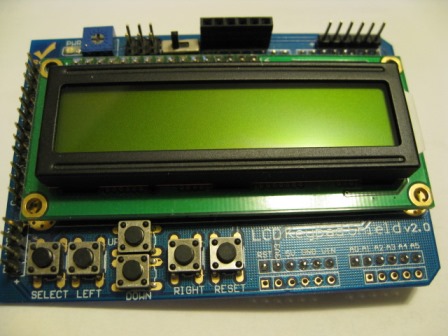
The demo for the board above is in your C:\GCstudio\GreatCowBASIC\demos\LCD_Solutions\Four_Wire_LCD_Solutions folder - YOU MUST look at the C:\GCstudio\GreatCowBASIC\demos\LCD_Solutions\Four_Wire_LCD_Solutions\Arduino_LCDShield folder as the cheapo boards from China have a short and you will damage your UNO. The folder shows the fix.
Hope this helps.
Last edit: Anobium 2022-09-18
I have seen a schematic somewhere which shows the Diode (D10) and where to to cut the print. - I can't find it !
I was going to modify these two over the weekend.
The diagrams and info are in the Help folders.
Thank you Evann, I read through this a while back and checked the Display Shields I have, I'm nearly sure I'm okay.
@ Stan. I am already using all my ports, as I/O Lines but I thought the Keypad buttons were all attached in series to AD10(AN0) and taken in as a voltage ?? I want to use the five keypad buttons.