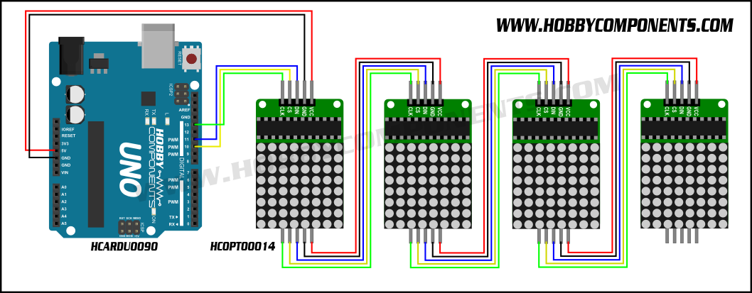
thanks for your explanation but this is what I mean;
just looking at the 8x8 devices on this picture: if your display(s) are connected in this way than there is no difference between your display and the one(s) I showed yesterday; either you buy and connect 4 devices or buy an already assembled device(for a much lower price).
Theo.
If you would like to refer to this comment somewhere else in this project, copy and paste the following link:
I choose not to display a diagram because stringing together devices may not work, if you purchase the devices from different suppliers. I have found that different suppliers have the LED MATRIX mounted at 0 degrees or 90 degrees. If you look at the library I have already written a 90 degree hanlder - should this be needed but all the matrixes need to be the same in terms of the mounting. Where all are 0 degrees or all are 90 degrees.
I have two sets already... different suppliers... different mounting.
That said.. the digram above is close enough apart from the pinouts - the Arduino library can use software or hardware SPI and the diagram above looks like a hardware SPI implementation.
If you would like to refer to this comment somewhere else in this project, copy and paste the following link:
One displays infp
DIY Kits
1 single module can drive an 8 * 8 dot matrix common cathode
2 module Operating voltage: 5V
3 Module dimensions: length 3.2 cm X 3.2 cm wide X 1.3 cm high
4 holes with four screws, diameter 3mm
5 modules with input and output interfaces, support for cascading multiple modules
Wiring instructions:
1 on the left block to an input port, an output port on the right.
2 When the control of a single module, simply enter the port received a CPU
When more than 3 modules cascaded output input termination CPU, the input output termination module of the first two modules of the first one, the first two modules of the termination input terminal of the three modules, and so on.
To 51 single example:
VCC → 5V
GND → GND
DIN → P2.2
CS → P2.1
CLK → P2.0
one display £1, four connected £4 ( like Anobiums)
If you would like to refer to this comment somewhere else in this project, copy and paste the following link:
Many thanks again. I have had zero success using the earlier (Hardware SPI only) version of this when trying to adjust it to work without PPS, and without hardware SPI. I did manage to 'bitbang' some code together from some very old (2012) code that Evan had re-written (from Ron Hackett's original version) for a PicAxe 08M2 that drove a four digit, seven segmant display. I modified this to drive the full 8 x 32 matrix and have it showing the uppercase alphabet - slowly yes, but it was a start. I thought it would be trivial to port this (working remember) program over to GCB but try as I might, it refuses to work. I'm sure I've made a daft error in the shift out routine:
SubShOutbbLetMaxLoad=0LetMaxClok=0LetOutWord_H=MaxRegLetOutWord=OutWord+OutByteForIndex=1to16IfOutWord.15=1ThenLetMaxData=1' set data to correspond to bit15ElseLetMaxData=0EndIfLetMaxClok=1' pulse clock lineWaitPulsTimeuSLetMaxClok=0WaitPulsTimeuSRotateOutWordLeft' shift left for next MSBNextIndexEndSubSubLoadDataLetMaxLoad=1' pulse clock lineWaitPulsTimeuSLetMaxLoad=0EndSub
But having spent most of today on it, I still can't see my mistake.
Still, I'll look again at this tomorrow and see if I can make any more sense of it.
[And I was so pleased with myself when I got the PicAxe version working too. Pride comes before a fall?]
Last edit: mkstevo 2018-01-29
If you would like to refer to this comment somewhere else in this project, copy and paste the following link:
The latest version has software SPI so things should work. Have a look at the library as the has the standard software SPI method - I simply copied from another library.
If you would like to refer to this comment somewhere else in this project, copy and paste the following link:
Thank you very much. One hour later and... It's alive. Yes, finally, I have my display showing 'It's alive'.
Now to crack on and see if I can use it and the 'matrix display' to replace my previous 4x4", seven segment displays.
Thanks to Anobium I'm progressing in the right direction at last. Eternal gratitude to you Anobium, and to all who work on developing GCB, I really appreciate it.
If you would like to refer to this comment somewhere else in this project, copy and paste the following link:
Yipee!!! I tested on Mega328p and an 18F hardware and software SPI - works.
Re 7-Segment. I think this is achieved by simply changing the font table. The font table is current 5 bytes so we would change to a single byte. The font table would be pretty simle to update then things would fall into place with the limitation that we only use GLCDPrintLn not all the GLCD commands. My initial thoughts.
If you would like to refer to this comment somewhere else in this project, copy and paste the following link:
Sorry. I may have mislead you regarding the seven segment comment. I'm hoping to 'patch in' the matrix display, into software written for a standard seven segment display. If feasible, and the display is quick enough, I may consider replacing the seven segment displays, with matrix displays. At the moment I'm not convinced the matrix displays update fast enough to replace the seven segment ones, but until I try, I'll never know.
If you would like to refer to this comment somewhere else in this project, copy and paste the following link:
Having got a 4 x MAX7219 display matrix working well, I tried cascading another, giving me 8 x MAX7219. I changed the definition in my program file to:
#defineMAX7219_X_Devices8
My text and display now scrolls along the display(s) correctly but the brightness appears only to be set on one of the devices, the one which is immediately connected to the PIC. The farthest one from the PIC (which displays the first characters of text) is set to a noticeably lower brightness level.
The command I use to set the brightness level is:
Max7219_LEDMatrix_Brightness(4)
I see in MAX7219_LEDMATRIX_Driver.h the code for setting the brightness level is:
I tried extending this from four 'sendByte' commands to eight to see if that would help, but still the same results. Display (A) dim, Display (B) bright.
Again, I'm sure I'm missing the obvious, but can't see where that might be. If anyone can suggest what I'm missing here, I'd be grateful of the advice.
No, sorry it doesn't seem to work any differently. The 'Farthest' display from the PIC is still at a low level of brightness, the 'Nearest' changes to the correct level.
I did try using the 'Repeat Max7219_Devices' technique when I tried to fix it myself and couldn't get it working either.
Interestingly (or not) if I set the number of devices to four, leaving the additional four connected in exactly the same way, the brightness does change on both, the text is then naturally duplicated on both displays. Which I'm sure also happened with the 'original' version.
If you would like to refer to this comment somewhere else in this project, copy and paste the following link:
I have changed the method to use a data stream, please retest.
If this fails then we wait until I get my next device, or, I resolve by further examination of the datasheet or someone else points us in the right direction. :-)
If you would like to refer to this comment somewhere else in this project, copy and paste the following link:
Sorry but I've left work for the weekend and have no displays with me at home. I will not be able to test until Monday/Tuesday now. Thank you for your input. I will report back once I've tested this.
If you would like to refer to this comment somewhere else in this project, copy and paste the following link:
Hello!
I now want to try running two LED Matrix modules using the Demo program code. But that does not work. Need some kind of resistors? I connect the modular pins directly to the microcontroller pin. the only thing I did in the program was to change the number of modules.
'Specifics for device configuration
  'Specifics for device configuration
  #define MAX7219_X_Devices 2
If you would like to refer to this comment somewhere else in this project, copy and paste the following link:
I yesterday tried GLCD KS0108 with a demo code. Display also did not want to work. But it could have been a waster. From China, goods often come out broken. I did not control contrast on the display. The display was completely empty, even dotted squares were not visible. Hmm, maybe these DOT MATRIX modules is broken? PIC worked :) china link 2 years ago :) ! I do not know why, but I am not able to add a photo. Insert Image - Then links appear.
If you would like to refer to this comment somewhere else in this project, copy and paste the following link:

Evan,
thanks for your explanation but this is what I mean;
just looking at the 8x8 devices on this picture: if your display(s) are connected in this way than there is no difference between your display and the one(s) I showed yesterday; either you buy and connect 4 devices or buy an already assembled device(for a much lower price).
Theo.
I choose not to display a diagram because stringing together devices may not work, if you purchase the devices from different suppliers. I have found that different suppliers have the LED MATRIX mounted at 0 degrees or 90 degrees. If you look at the library I have already written a 90 degree hanlder - should this be needed but all the matrixes need to be the same in terms of the mounting. Where all are 0 degrees or all are 90 degrees.
I have two sets already... different suppliers... different mounting.
That said.. the digram above is close enough apart from the pinouts - the Arduino library can use software or hardware SPI and the diagram above looks like a hardware SPI implementation.
One displays infp
DIY Kits
1 single module can drive an 8 * 8 dot matrix common cathode
2 module Operating voltage: 5V
3 Module dimensions: length 3.2 cm X 3.2 cm wide X 1.3 cm high
4 holes with four screws, diameter 3mm
5 modules with input and output interfaces, support for cascading multiple modules
Wiring instructions:
1 on the left block to an input port, an output port on the right.
2 When the control of a single module, simply enter the port received a CPU
When more than 3 modules cascaded output input termination CPU, the input output termination module of the first two modules of the first one, the first two modules of the termination input terminal of the three modules, and so on.
To 51 single example:
VCC → 5V
GND → GND
DIN → P2.2
CS → P2.1
CLK → P2.0
one display £1, four connected £4 ( like Anobiums)
Many thanks again. I have had zero success using the earlier (Hardware SPI only) version of this when trying to adjust it to work without PPS, and without hardware SPI. I did manage to 'bitbang' some code together from some very old (2012) code that Evan had re-written (from Ron Hackett's original version) for a PicAxe 08M2 that drove a four digit, seven segmant display. I modified this to drive the full 8 x 32 matrix and have it showing the uppercase alphabet - slowly yes, but it was a start. I thought it would be trivial to port this (working remember) program over to GCB but try as I might, it refuses to work. I'm sure I've made a daft error in the shift out routine:
But having spent most of today on it, I still can't see my mistake.
Still, I'll look again at this tomorrow and see if I can make any more sense of it.
[And I was so pleased with myself when I got the PicAxe version working too. Pride comes before a fall?]
Last edit: mkstevo 2018-01-29
The latest version has software SPI so things should work. Have a look at the library as the has the standard software SPI method - I simply copied from another library.
Thank you very much. One hour later and... It's alive. Yes, finally, I have my display showing 'It's alive'.
Now to crack on and see if I can use it and the 'matrix display' to replace my previous 4x4", seven segment displays.
Thanks to Anobium I'm progressing in the right direction at last. Eternal gratitude to you Anobium, and to all who work on developing GCB, I really appreciate it.
Yipee!!! I tested on Mega328p and an 18F hardware and software SPI - works.
Re 7-Segment. I think this is achieved by simply changing the font table. The font table is current 5 bytes so we would change to a single byte. The font table would be pretty simle to update then things would fall into place with the limitation that we only use GLCDPrintLn not all the GLCD commands. My initial thoughts.
Sorry. I may have mislead you regarding the seven segment comment. I'm hoping to 'patch in' the matrix display, into software written for a standard seven segment display. If feasible, and the display is quick enough, I may consider replacing the seven segment displays, with matrix displays. At the moment I'm not convinced the matrix displays update fast enough to replace the seven segment ones, but until I try, I'll never know.
I have an oddity with the display(s).
Having got a 4 x MAX7219 display matrix working well, I tried cascading another, giving me 8 x MAX7219. I changed the definition in my program file to:
My text and display now scrolls along the display(s) correctly but the brightness appears only to be set on one of the devices, the one which is immediately connected to the PIC. The farthest one from the PIC (which displays the first characters of text) is set to a noticeably lower brightness level.
The command I use to set the brightness level is:
I see in MAX7219_LEDMATRIX_Driver.h the code for setting the brightness level is:
I tried extending this from four 'sendByte' commands to eight to see if that would help, but still the same results. Display (A) dim, Display (B) bright.
Again, I'm sure I'm missing the obvious, but can't see where that might be. If anyone can suggest what I'm missing here, I'd be grateful of the advice.
Last edit: mkstevo 2018-02-02
My error. As I dont have two devices - yet! I will have lots soon.
Please try this https://github.com/Anobium/Great-Cow-BASIC-Library-Development/tree/master/MAX7219-LEDMATRIX-GLCD_Driver/Prototype%20Library001
Test as 4x1 and 8x1 and post results.
Anobium
No, sorry it doesn't seem to work any differently. The 'Farthest' display from the PIC is still at a low level of brightness, the 'Nearest' changes to the correct level.
I did try using the 'Repeat Max7219_Devices' technique when I tried to fix it myself and couldn't get it working either.
Interestingly (or not) if I set the number of devices to four, leaving the additional four connected in exactly the same way, the brightness does change on both, the text is then naturally duplicated on both displays. Which I'm sure also happened with the 'original' version.
I have changed the method to use a data stream, please retest.
If this fails then we wait until I get my next device, or, I resolve by further examination of the datasheet or someone else points us in the right direction. :-)
Sorry but I've left work for the weekend and have no displays with me at home. I will not be able to test until Monday/Tuesday now. Thank you for your input. I will report back once I've tested this.
I have updated. I have changed the method extensively. If works on the 1x4 here. (Still no delivery!). Please test.
I am, as ever grateful for you looking at this.
I can report that the most recent code is certainly working correctly on my eight Max7219 units, cascaded into an 8 x 64 display.
Many thanks.
Excellent. I could not test but the theory worked!
And, thank for the photo!
I'll upload a video later. It's too large for SourceForge.
So. If I've done this right, this should show some demo text scrolling across the two linked displays: https://www.youtube.com/watch?v=DMyvaV2rJnI
Last edit: mkstevo 2018-02-05
Hello!
I now want to try running two LED Matrix modules using the Demo program code. But that does not work. Need some kind of resistors? I connect the modular pins directly to the microcontroller pin. the only thing I did in the program was to change the number of modules.
'Specifics for device configuration
Yes, I also use the same PIC16F18855 used in the demo code.
How odd. Should work.
Does one LED Matrix operate as expected?
Not. both the one and the other module blinking some times and that's all. :(
Can you post a photo of the module? and, a link to the product?
I yesterday tried GLCD KS0108 with a demo code. Display also did not want to work. But it could have been a waster. From China, goods often come out broken. I did not control contrast on the display. The display was completely empty, even dotted squares were not visible. Hmm, maybe these DOT MATRIX modules is broken? PIC worked :) china link 2 years ago :) ! I do not know why, but I am not able to add a photo. Insert Image - Then links appear.
You may have to created the post, then, edit the post to attach items - then, save.
Yess