rp6simul Home
rp6simul is a simulator for the RP6 robot (AREXX Engineering)
Brought to you by:
rick_helmus
rp6simul manualIn this manual you will learn how you can use rp6simul to simulate
your RP6 and/or m32 AVR projects. The manual is setup like a tutorial or 'howto',
as it will describe and illustrate the steps needed to for a specific task.
More information on the rp6simul project can be found on the project homepage
Before you can perform any simulations, you have to make sure that your project
code is suitable to load in to the simulator. Unlike some AVR simulators,
rp6simul does not handle native AVR code, but instead you will need to compile
your code natively. In practise this means that instead of creating a hex file,
you will now compile a 'plugin file', which is simply a shared or dynamic
library (i.e. a .dll file or .so file). Note that for the RP6 and m32 a
separate plugin file is used (just like you would use individual .hex files).
When you have produced your plugin file, you will need to tell the simulator where to find it. This is performed by creating a new simulator project. These projects are nothing more than simple text files (ini formatting) that hold information about what to simulate (i.e. RP6, m32 or both), the file path to your plugin file(s) and some more specific options. All these options can be easily set through the user interface of the simulator.
When you made your project you are pretty much done, and pressing the 'run' button will start running the code defined in your plugin file(s). At this point, it is possible to open a 2d environment (i.e. a map file) and let your robot wander through a virtual 2d world, where it can interact with several obstacles and varying light levels.
The rest of this manual will describe in detail the steps that need to be done to build your plugin file(s), create a new project, and deal with virtual worlds. It finishes with some notes on more advanced features, such as serial port pass through, and creating your own drivers to control new peripherals (e.g. sensors).
As was briefly mentioned in the previous section, rp6simul does not simulate
native AVR code, but you will need to compile your code natively to produce a
plugin file. This plugin file is simply a shared (or dynamic) library that is loaded
by the simulator.
Before you can start compiling with your favorite compiler, we first need to make
sure to provide some AVR specific functionality, most importantly the IO registers
that are used to control the hardware. These things are obviously specific to AVR
microchips, and are not provided by a typical desktop computer. Furthermore, avr-libc
also provides a few utility functions that may not be present with your compiler. This
functionality is provided by avrglue, which is a set of source files that define
most of the IO registers, and other avr-libc functionality (such as PROGMEM). Moreover,
avrglue provides communication between your AVR code and the simulator, thereby
'gluing' the AVR specific code to the simulator.
Another important change compared to producing regular .hex files, is that the
native code needs to be compiled as C++ code. This is required in order to
provide a simple and effective way to monitor all IO register access. Luckily, C++
is in general compatible to your average C code. However, sometimes C++ is more
strict, and for this reason, a few small changes had to be made to the RP6 library
provided by AREXX. These changes are generally minor, and the modified library can
still be used without problems on native AVR hardware. Note that it is unlikely
that you will need to modify your own code, so in most cases you should be able
to use your robot code with the simulator or on actual hardware.
To simplify building plugins, it is recommended to use the plugins-src package
(available on the project homepage). This source archive contains the
aforementioned avrglue files, a RP6 library that incorporates the fixes required
to build the code as native C++, and a build file that links your robot code to
the former two. This build file, is a cmake build file, and is called CMakeLists.txt.
In order to process it you will need cmake. As will be illustrated below,
using cmake will simplify the building process, and you can use it to easily
configure the building process to your needs. For both the RP6 and m32 a specific
CMakeLists.txt file is provided.
So that's it for the theory, lets now start to do the actual work to make your plugin files available for simulation. Don't worry, this should be pretty straightforward, and I have taken special care to make this as easy (but flexible) as possible.
In order to build plugin files, the following things are needed:
gcc, on Windows I have only
tested MinGW. So to keep things easy, try to use either of these two.plugin-src package that can be downloaded from the project homepage.If you are on Windows, and need to install MinGW, please be sure to carefully
read the installation instructions. Here are some notes:
MinGW, so you can disable the installation of MSYS and
others,C:\MinGW),bin directory (e.g. C:\MinGW\bin) to
the PATH environment variable.The installation process of MinGW is a bit tricky compared to most other
Windows software, but by keeping the above notes in mind, and carefully reading
the installation instructions, everything should be fairly straightforward.
Once you have obtained these requirements, the next thing is to extract the
plugins-src archive. If everything went well, you will now have a directory
called rp6simul-plugin that that contains the following sub-directories:
It is now time to launch cmake. This program can be operated either via the commandline,
or you can use a nice graphical user interface called cmake-gui. In this manual,
I will focus on the latter option. Furthermore, I will solely focus on building a
RP6 plugin. To build a m32 plugin you will need to follow the same steps, and
the only difference is that you need to use the CMakeLists.txt from
the m32/ directory.
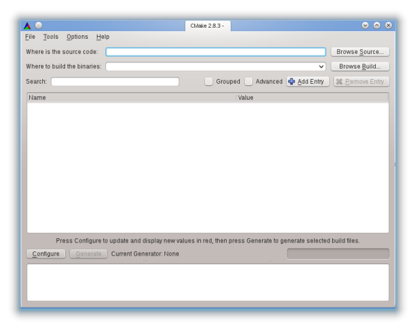
Now go ahead and launch the cmake-gui program. If everything went well the
following screen should appear (this guide assumes version 2.8.3):
Now select the source directory. In our case this is the rp6/ sub-directory
within the rp6simul-plugin/ directory. In order to avoid cluttering up the
source directory, it is best to chose a different binary directory. This directory
is used to generate object files and the plugin file. Another reason to why keeping
the binary directory separate, is that you could place the 'regular' AVR Makefiles
and such in the source directory, without interfering the simulator build
process. In this guide we select a new subdirectory called build/ within the
rp6/ directory (i.e. rp6simul-plugin/rp6/build). You can leave all the other
options as they are. Now press Configure and
(depending on your system) the following dialog will appear:
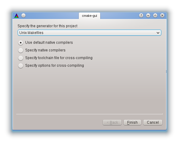
If you use gcc, chose Unix Makefiles, while MinGW users should chose
MinGW Makefiles. In both cases you most likely want to use the default native
compilers. After pressing Finish we return at the main screen.
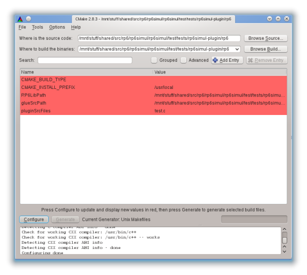
The next thing is to select the plugin source files. Before doing so, it is
easy to copy your AVR C source code files to the rp6/ directory. Most often,
the source is nothing more than one file that ends with .c. By default, it is
assumed that the name of this file equals test.c. However, if your source
file is named differently, you will need to modify the pluginSrcFiles
(the bottom field in the screenshot above). You can enter multiple files by
separating them with a semicolon (;). After you applied any changes to
pluginSrcFiles you will need to press Configure again. All that remains is
pressing Generate to generate the Makefiles in the build/ directory.
If everything went well, you are now ready to compile the plugin. To do so,
open a terminal (Windows users: a 'DOS window'), cd to the rp6/build/ directory
and run make (or mingw32-make if you use use MinGW). As a result, you should
now have your plugin file that is named either libplugin.so (Linux) or
libplugin.dll (Windows). Note that if you make any source code changes after
compilation, you only need to run this make step to update the plugin file.
After you have successfully build your plugin file(s), it is now time to create
a simulator project. This project keeps a few settings such as the location of
your plugin file(s) and which things to simulate (RP6, m32 or both). To do so,
install & launch rp6simul, go to File, New Project and the following screen
should appear:
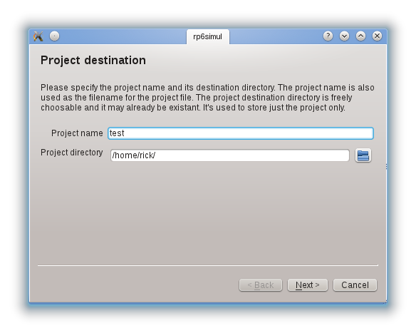
Select a project name (keep it simple as it will be used as a base for the
project file name) and specify a destination directory. After pressing Next,
you can now select what you want to simulate. Since we are following the example
from the previous section, select RP6 here. In the next screen select the plugin
file (i.e. libplugin.so or libplugin.dll) and press Finish. Note that you
can change these and other settings from the Project Settings option under
the Edit menu. The project should now be automatically loaded and you are
greeted with the following screen:
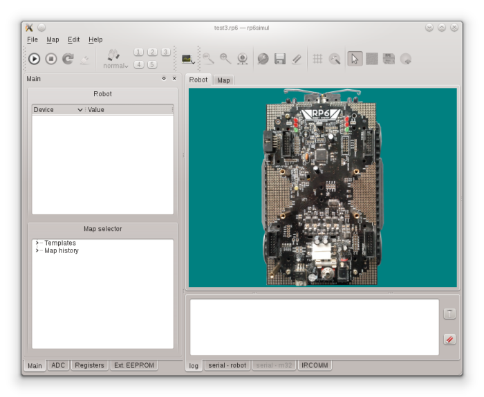
As a quick test press the Run button ( ). If your
robot moves (which isn't uncommon) it is also nice to open a map (more on this
later). To do, unfold the Templates tree item from the Map selector
(bottom-left in the screenshot above) and chose any map you like. If you want to
view serial output, or input any serial data, activate the serial - robot tab
at the bottom of the screen.
). If your
robot moves (which isn't uncommon) it is also nice to open a map (more on this
later). To do, unfold the Templates tree item from the Map selector
(bottom-left in the screenshot above) and chose any map you like. If you want to
view serial output, or input any serial data, activate the serial - robot tab
at the bottom of the screen.
The end of the last section already briefly introduced how to let your robot move in a virtual world by opening a map file. This section contains a more detailed overview on how to open-, create- and use maps.
A map file represents a two-dimensional virtual world where the robot can move. As can be expected, the use of map files is only possible when the RP6 robot is simulated, and therefore is disabled when only the m32 is active. To view the current map file open the Map tab in top center of the main screen.
Besides letting the robot move, a map file is also useful to test how your code reacts on the environment. For this purpose, the following items can be placed inside a map:
Boxes and walls are useful to see how your robot reacts to collisions. Light items are used to create varying light levels within the environment. Unlike box items, wall items will block the illuminating light from a light entity, thereby creating shadows. An example of a typical map that features these items is shown below.
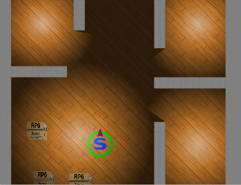
The blue 's' with the green circle around it is the starting point of the map. Each map will have one of these items, and as soon as you hit the Run button the robot will start to move at this position. Furthermore, the small arrow (in the screenshot at the top) signifies the angle at which the robot will start.
To open a map, you have two choices: use the Map selector or the Load map
option from the Map menu. Using the former option, you can select a map from the
Map history or a map template (discussed below). The Load map option lets
you select any map file stored locally. These map files can be recognized by
their .map extension.
A quick way to open a ready-to-use virtual environment is by loading a map template. These can be selected from the Map selector (which is found in the Main dock widget). Several templates exist with varying size and complexity. Although map templates can be modified, they cannot be stored, and if you try you are asked to save the map under a different file name.
Once you loaded a map (or map template) the map viewer (i.e. the map tab on the
top-center) is automatically shown, and by pressing the Run button
() the robot will start to move within its
virtual environment.
Creating new maps is performed with the New map option in the map menu. A simple dialog option shows up in which you can specify the map size, its name and its destination directory.
Map editing is quite simple and can even be performed while the plugin(s) are running. All the map edit actions are available on the Edit map toolbar:

Note that this toolbar is only enabled when the mapview is activated.
Adding walls, boxes and lights is performed by clicking one the far right options. If one of these options is enabled, your mouse cursor will change in a crosshair. To add the selected item, hover your cursor to the starting point, click and hold the left mouse button, and drag towards the end point. When the left mouse button is released the item is added to the map. When you are done you can either click the arrow button of the map toolbar, or press the right mouse button. and by clicking and holding the left mouse.
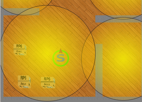
As you may have noticed, by default you cannot add any lights. If you want to
add (or edit) light items, you will need to activate light edit mode
( ). The result is that lighting effects are
disabled, and all light items are visible as circles:
). The result is that lighting effects are
disabled, and all light items are visible as circles:
If you want to move or resize items you first must select them with a left mouse click. Resizing a light item, i.e. increasing or decreasing its radius, is done by a small handle that appears in the center:
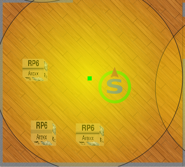
By clicking and dragging this handle, the radius of the light will be changed.
To delete an item, either press the Delete key on your keyboard, or right click on an item and select Delete from the menu that pops up.
Similar to other items, the robot start item can also be moved. Furthermore, after selecting it you can also rotate it by dragging one of the four handles that appear. By moving or rotating this item, you can influence the start position and rotation of the robot when you activate the plugin. Note that you cannot delete the robot start item.
Some of the map properties can be changed by activating the map settings dialog
( ). Here you can change for instance the map
size or the ambient light (i.e. the light level in absence of lighting by
a light item).
). Here you can change for instance the map
size or the ambient light (i.e. the light level in absence of lighting by
a light item).
When you have loaded a map that you are satisfied with and you started your
plugin(s), you can see how your robot behaves within the virtual environment. A
nice way to do so is by enabling robot following
( ).
).
You can also interact with the robot. As was mentioned earlier, the map can be edited while the robot is active, therefore you can for instance add or move a box and see how the robot reacts. In fact, it is even possible to change the current map while the robot is running. It is also possible to interact with the robot itself. If you select the robot (using the left mouse button), the robot cannot move, however, similar to what happens when you would pickup the robot, the motors will continue run freely. By pressing the right button on the robot, a simple menu pops up where you can permantly lock the robot, and quickly rotate it. You can also rotate the robot by selecting it, and dragging one of the four handles that appear.
The previous sections outlined the most commonly performed tasks with rp6simul.
This section will briefly outline some of the more advanced features.
When you have m32 simulation enabled, you can press the hand clap button
( ) to generate a clapping noise.
This noise will be registered by the MIC ADC channel of the m32 board. The
sound level can be influenced by pressing and holding the hand clap button for a
shot while.
) to generate a clapping noise.
This noise will be registered by the MIC ADC channel of the m32 board. The
sound level can be influenced by pressing and holding the hand clap button for a
shot while.
The simulator is able to simulate the serial ports for both the RP6 and m32.
Moreover, it is also possible to link the simulated ports to a physical or virtual
serial port (e.g. a COM port). This is most useful if you wrote a program that
interacts with your robot via its serial port. In such a case, you can install
a virtual serial port on your system (e.g. socat on Linux or com0com
on Windows).
To enable serial pass through you must first specify the port within
the Preferences dialog that is accessible via the Edit menu. After doing so,
press the serial pass through button
( ) to link the simulated serial
port with the port you specified earlier.
) to link the simulated serial
port with the port you specified earlier.
The simulation of all the peripherals on the robot and m32 (e.g. sensors, ADC)
are each controlled by drivers. These drivers are nothing more than simple Lua
scripts, which try to do their best to simulate the real hardware. From the
project settings you can specify which drivers you want to use, but it is best
to keep the defaults since some drivers are mandatory. Furthermore, you can also
add new custom drivers to extend the functionality of the simulator.
Editing or creating a new driver is simplified by the use of Lua (Lua), which
is a simple, easy to learn, and easily readable scripting language. If you want
to know more about the driver interface, it is best to learn from the existing
drivers (the various .lua files found within the src/ directory of rp6simul).
Even though the use of Lua greatly simplifies driver development, if you need to
extend the user interface you still need to modify the C++ source of the main
program.
If you are interested in driver development, or created or modified a driver, feel free to contact me!
Several other features exist. For instance, you can override ADC values by using the ADC dock widget and modify the external EEPROM from the m32 by using the Ext. EEPROM dock widget. These and other features are mostly self-explanatory from the user interface, and it is best to just experiment a little.
