The following questions were sent to me by mail from gera. I publish these here with gera's consent to allow others to participate in the discussion.
Here is the original STL file that wouldn't open with PyCAM attached.
Aside from not opening, I fixed it with MeshCAM by disabling binary. But would like to ask what is the best way to make it work? Or how would you make it work?
Also, generating the G-Code for this file takes rather so long I had to cancel it.
While I do not need it to be super precise (so I put 0 for material allowance for the rough which would make it the exact size I want it right?), I think all I need is a rough operation, no other.
Material allowance: yes, you want zero
The usual minimum set of operations (for 3D) is roughing and then surfacing.
You will see the difference when you try it: roughing moves at fixed layer heights. There will be still some material left. The surfacing process fixes this.
Alternatively you can also skip the roughing process if you think that the tool can go down through the complete height of the stock material at once.
Still don't know exactly what material allowance is and would like you to explain it to me.
Material allowance is the amount of material to be left around the model. Use it if your tool is known for leaving rough edges.
Also what is overlap? I didn't really understand the explanation given in the help. Do I need it for this particular thing I am cutting?
Consider parallel tool moves with a given tool radius. The distance between these parallel lines is 2*r for overlap=0%. An overlap of 25% would reduce this distance to 1.5*r.
Did you refer to the help in the wiki? Please consider improving the wording there to help others as well.
This is going to be cut on MDF wood and I don't know what feed speed I would be able to cut it at without breaking the tool bit or anything. The router is capable of 35k rpm with variable settings form 5kRPM-35k rpm. I heard it's best to keep it as high as possible. Is that correct? Why?
Now you entered the interesting process of getting to know your tools and your material :)
I can't really give you answers that will suit your situation.
Here I am cutting through MDF with a feedrate of around 1400mm/min. The spindle rotation depends on your tool: slower for big ones and faster for thin tools.
The tool diameter will be .25" (Yes rather small, but I'll just use it anyway) and all I need is a roughing operation done. I think the offset will be .125" or half the toolbit diameter, correct?
Since your model (not available for other readers here - sorry) is just a 2D model with a given height, it would be more efficient to use a contour (waterline) algorithm. This would result in efficient cuts around the model. A roughing operation would remove all unnecessary material instead (this consumes much more machine time).
How can I convert the G-Code in a way so that the program does not take so long?
As usual in engineering life you need to prepare well if you want to use your tools efficiently :)
In this specific case you probably have three options:
- use a roughing process (fast calculation, acceptable accuracy, very slow machine operation)
- use a contour process (slow calculation, acceptable accuracy, fast machine operation)
- create a 2D projection of your model and use "engrave" with engrave_offset=tool_radius (fast calculation, perfect accuracy, fast machine operation)
experimenting helps …
Or why does it take so long to generate G-Code with PyCAM?
Because the development is currently focussed on features and not on performance.
In February two helpful committers joined and improved the performance tremendously.
In short: PyCAM is slow in some regards because there is currently no one working on this specific field. Whoever jumps in and helps with documentation, support communication and coding will improve the chance that the performance sooner gets better.
Will it take that long with other CAM programs?
I don't use other software - so I can't tell.
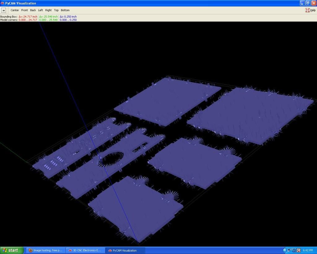
Also when opening an STL file in PyCAM, on the drawing I see a bunch of lines sticking out of it. What is that?
There are the three coordinate axes (red, green, blue) in the drawing. I am not aware of other lines. Just prepare a screenshot so someone can help you.
The above STL file drawings were obtained from DIYLILCNC.org and the cut parts will be used to assemble an enclosure where a hobbycnc.com Pro unipolar chopper driver board and all the electronics for that board will be inserted.
diylilcnc is a really interesting project - good luck with the assembly!
If you would like to refer to this comment somewhere else in this project, copy and paste the following link:
I do not know how to apply that patch manually. There are no downloads there and I know rather nothing about program, so I would need help.
Material allowance: yes, you want zero
The usual minimum set of operations (for 3D) is roughing and then surfacing.
You will see the difference when you try it: roughing moves at fixed layer heights. There will be still some material left. The surfacing process fixes this.
Alternatively you can also skip the roughing process if you think that the tool can go down through the complete height of the stock material at once.
For roughing there will still be some material left where? Probably not on the outsides because material allowance is set to 0.
Some material left on the bottom?
And yes I do need to cut at fixed layer heights to avoid breaking the tool.
The surfacing process, while you explained what I can use it for, can you explain what the surfacing process does or what its purpose is?
Consider parallel tool moves with a given tool radius. The distance between these parallel lines is 2*r for overlap=0%. An overlap of 25% would reduce this distance to 1.5*r.
Did you refer to the help in the wiki? Please consider improving the wording there to help others as well.
I think I understand what overlap is now :). If I wanted to say cut a sphere, I would put overlap really high to make a shape that is more round where the tool would not move it's entire diameter to the next path, but only a certain percentage of its diameter to each next path. Kind like a resolution size. Is this right?
Since your model (not available for other readers here - sorry) is just a 2D model with a given height, it would be more efficient to use a contour (waterline) algorithm. This would result in efficient cuts around the model. A roughing operation would remove all unnecessary material instead (this consumes much more machine time).
For contour in PyCAM, I do not see a "waterline" contour, I only see 2 countours: A polygon contour and a follow contour.
Also does contour have step down or cutting a fixed layer heights like roughing?
In this specific case you probably have three options:
- use a roughing process (fast calculation, acceptable accuracy, very slow machine operation)
- use a contour process (slow calculation, acceptable accuracy, fast machine operation)
- create a 2D projection of your model and use "engrave" with engrave_offset=tool_radius (fast calculation, perfect accuracy, fast machine operation)
experimenting helps …
I have a 2D projection of my model, but what if I need step down, or like you say cut in fixed layer heights? How would that work with a 2D drawing? Is that possible?
There are the three coordinate axes (red, green, blue) in the drawing. I am not aware of other lines. Just prepare a screenshot so someone can help you.
Here are the lines I was talking about:
Does this forum have an edit button?
If you would like to refer to this comment somewhere else in this project, copy and paste the following link:
I do not know how to apply that patch manually. There are no downloads there and I know rather nothing about program, so I would need help.
In this case you can do it manually (it is only one line replaced with another). Just take a look at the patch: you will find the filename at its top. Search for this filename in your system and open the file with a text editor (wordpad is a good choice in Windows).
Then you just search for the piece of text given in the patch (alternatively you can look for the line number that is also given in the head of the patch). Then you change the content of the line prefixed with "-" to the line prefixed with "+".
Even though a patch is made to be applied via a program ("patch") you can also understand it plainly. It is simple - just stare at it for five minutes and you will understand …
(or just use meshlab as a temporary workaround)
For roughing there will still be some material left where? Probably not on the outsides because material allowance is set to 0.
Some material left on the bottom?
And yes I do need to cut at fixed layer heights to avoid breaking the tool.
The surfacing process, while you explained what I can use it for, can you explain what the surfacing process does or what its purpose is?
I could try to explain this now - but it would take much longer than some quick experiments on your side.
Just load one of the simple models in the "samples" directory and experiment with the processes. This takes seconds to compute and only some minutes to grasp the differences.
(also take a look at the manual: http://sourceforge.net/apps/mediawiki/pycam/index.php?title=ProcessSettings)
Overlap like a resolution size. Is this right?
yes - that is the best word for it!
For contour in PyCAM, I do not see a "waterline" contour, I only see 2 countours: A polygon contour and a follow contour.
"waterline" is just another word for contour processes. Usually the polygon contour is ok for most purposes but you may want to use the follow algorithm in specific cases. The differences are subtile and hard to explain.
Also does contour have step down or cutting a fixed layer heights like roughing?
The contour algorithm allows you to specify a step_down value - thus you will get multiple layers of toolpaths.
I have a 2D projection of my model, but what if I need step down, or like you say cut in fixed layer heights? How would that work with a 2D drawing? Is that possible?
These lines are visible after enabling the "show directions" option. The lines are the normals of the triangles - they can be used for debugging broken models. Just disable the option - probably you don't need it.
Does this forum have an edit button?
As far as I can tell: no :(
PS: in general: if you think that the manual needs more details or some clarification: just be bold and fix it. Thanks!
If you would like to refer to this comment somewhere else in this project, copy and paste the following link:
For contours, I cannot choose engrave offest and set it. Does it offset the tool automatically by itself without the need of setting engrave offset?
I want to try to generate G-Code in every one of those settings you suggested just for experimentation and because I have both a 3D and a 2D visualization of my parts.
Also it asks for grid direction, some other options ask for x or y or both. I really don't understand this it feels to me like I need both because if I just choose 1 I have a feeling that it will cut only on that axis and it just doesn't make sense. I don't think I understand grid direction correctly so please explain it.
If you would like to refer to this comment somewhere else in this project, copy and paste the following link:
Ahh another question about engraving offset.
A negative path shifts the tool toward the inside….
The way I see it is it can only be offset in 1 direction, either inside or outside.
I would use a negative offset to cut circles on the inside to make holes, but what if I want to cut on the outsides too?
I need both operations in this particular part. As you can see there are half circles on this part on the edge, those I need to cut on the outside not inside.
If you would like to refer to this comment somewhere else in this project, copy and paste the following link:
Wish this forum had an edit button so look at all the posts I posted but:
Experimenting with converting G-Code using a 2D model, pycam generates G-Code just fine with a negative offset value, but one problem: the offsets are not on the right side in certain areas.
However when setting a positive offset value, PyCAM freezes and I end up having to restart it.
If you would like to refer to this comment somewhere else in this project, copy and paste the following link:
For contours, I cannot choose engrave offest and set it. Does it offset the tool automatically by itself without the need of setting engrave offset?
Did you try this already? Just take one of the simple 3D models in the /samples/ directory. You will see easily that the tool will run around the model in the appropriate distance.
The 2D operation ("engrave") is the only one where it is not clear if and how a tool radius should influence the toolpath. For 3D operations it is quite obvious that the tool should not cut through a valuable and well-shaped model :)
I want to try to generate G-Code in every one of those settings you suggested just for experimentation and because I have both a 3D and a 2D visualization of my parts.
This is my preferred way of learning, as well …
Also it asks for grid direction, some other options ask for x or y or both. I really don't understand this it feels to me like I need both because if I just choose 1 I have a feeling that it will cut only on that axis and it just doesn't make sense. I don't think I understand grid direction correctly so please explain it.
hehe - this one is really easy to spot - just create three toolpaths with these three options. You will understand it in a second.
Ahh another question about engraving offset.
A negative path shifts the tool toward the inside….
The way I see it is it can only be offset in 1 direction, either inside or outside.
I would use a negative offset to cut circles on the inside to make holes, but what if I want to cut on the outsides too?
I need both operations in this particular part. As you can see there are half circles on this part on the edge, those I need to cut on the outside not inside.
Wish this forum had an edit button so look at all the posts I posted but:
Experimenting with converting G-Code using a 2D model, pycam generates G-Code just fine with a negative offset value, but one problem: the offsets are not on the right side in certain areas.
I have to admin that this part of 2D modelling is not obvious.
To put it simple: the direction of each polygon determines if it marks the "inside" or "outside" edge of the model. But most 2D drawing programs do not care about this (not officially specified) interpretation.
Now you have two options: use your 2D drawing program (e.g. Inkscape) do reverse the direction of each polygon that is "wrong" (according to your expectation). Alternativly you can also just try the "revise directions" button in PyCAM. It triggers a quite simple but helpful detection of inside/outside polygons and reverses them as needed. For now I never encountered a model where it failed.
Anyway: you should also take a look at the User Manual - there is a section about 2D modelling. This is all explained there: http://sourceforge.net/apps/mediawiki/pycam/index.php?title=Hints_for_2D_modeling_with_Inkscape_(SVG)
However when setting a positive offset value, PyCAM freezes and I end up having to restart it.
Yes - PyCAM's 2D offsetting is known to be problematic. Usually it works, but it is not completely stable. Just try it again with a slightly different offset value (e.g. use 1.00001 instead of 1.0). This will get better within some months, I guess.
If you would like to refer to this comment somewhere else in this project, copy and paste the following link:
Recently discovered PyCam within thee last month or so and have confronted the same issues…. wich this thread has helped me resolve… export my FreeCAD drawing as a .STL to flash (basically memory), Import it into MeshCAM, Do the save thing or Export thing…wich ever allows you to disable binary…sent that file to flash, open PyCAM and open the MeshCAM .STL model with the binary disabled…and YAY! Finally! there it is my sweet FreeCAD 3D drawing in the PyCAM 3D viewer window…But now I can't get the generated tool path to show up… BUT it will show the path and give me G when I I use the same "process" on the PYCAM block thing demo model…Please Help, thanks
If you would like to refer to this comment somewhere else in this project, copy and paste the following link:
Oshuab, just do the manual patch. It's really easy and will avoid you future problems in having to convert files and disable binary. If you do the patch, you won't have to do that conversion.
If you would like to refer to this comment somewhere else in this project, copy and paste the following link:
yes - "nobody" is right: just apply the above patch if you want to import binary STL files into PyCAM.
The next release will include this fix.
Regarding the empty toolpath: please open a new forum thread for this discussion.
Just a quick hint: please check the size of your model (at the top of the 3D window). Maybe the model is just too small for the default tool size?
cheers,
Lars
If you would like to refer to this comment somewhere else in this project, copy and paste the following link:
I there some easy way to find that patch to change in my system? I ave pycam on my flash drive but don't know where to find the patch….Please help, thanks…
If you would like to refer to this comment somewhere else in this project, copy and paste the following link:
The following questions were sent to me by mail from gera. I publish these here with gera's consent to allow others to participate in the discussion.
Thanks for sending the DXF file. I found the source of the problem and committed the fix. You will need to wait for the next release or just apply the following patch manually:
http://pycam.git.sourceforge.net/git/gitweb.cgi?p=pycam/pycam;a=commitdiff;h=9ae1d60db199ac3dbd749b3c97f9a15534faf217
Material allowance: yes, you want zero
The usual minimum set of operations (for 3D) is roughing and then surfacing.
You will see the difference when you try it: roughing moves at fixed layer heights. There will be still some material left. The surfacing process fixes this.
Alternatively you can also skip the roughing process if you think that the tool can go down through the complete height of the stock material at once.
Material allowance is the amount of material to be left around the model. Use it if your tool is known for leaving rough edges.
Consider parallel tool moves with a given tool radius. The distance between these parallel lines is 2*r for overlap=0%. An overlap of 25% would reduce this distance to 1.5*r.
Did you refer to the help in the wiki? Please consider improving the wording there to help others as well.
Now you entered the interesting process of getting to know your tools and your material :)
I can't really give you answers that will suit your situation.
Here I am cutting through MDF with a feedrate of around 1400mm/min. The spindle rotation depends on your tool: slower for big ones and faster for thin tools.
Since your model (not available for other readers here - sorry) is just a 2D model with a given height, it would be more efficient to use a contour (waterline) algorithm. This would result in efficient cuts around the model. A roughing operation would remove all unnecessary material instead (this consumes much more machine time).
As usual in engineering life you need to prepare well if you want to use your tools efficiently :)
In this specific case you probably have three options:
- use a roughing process (fast calculation, acceptable accuracy, very slow machine operation)
- use a contour process (slow calculation, acceptable accuracy, fast machine operation)
- create a 2D projection of your model and use "engrave" with engrave_offset=tool_radius (fast calculation, perfect accuracy, fast machine operation)
experimenting helps …
Because the development is currently focussed on features and not on performance.
In February two helpful committers joined and improved the performance tremendously.
In short: PyCAM is slow in some regards because there is currently no one working on this specific field. Whoever jumps in and helps with documentation, support communication and coding will improve the chance that the performance sooner gets better.
I don't use other software - so I can't tell.
There are the three coordinate axes (red, green, blue) in the drawing. I am not aware of other lines. Just prepare a screenshot so someone can help you.
diylilcnc is a really interesting project - good luck with the assembly!
I do not know how to apply that patch manually. There are no downloads there and I know rather nothing about program, so I would need help.
For roughing there will still be some material left where? Probably not on the outsides because material allowance is set to 0.
Some material left on the bottom?
And yes I do need to cut at fixed layer heights to avoid breaking the tool.
The surfacing process, while you explained what I can use it for, can you explain what the surfacing process does or what its purpose is?
I think I understand what overlap is now :). If I wanted to say cut a sphere, I would put overlap really high to make a shape that is more round where the tool would not move it's entire diameter to the next path, but only a certain percentage of its diameter to each next path. Kind like a resolution size. Is this right?
For contour in PyCAM, I do not see a "waterline" contour, I only see 2 countours: A polygon contour and a follow contour.
Also does contour have step down or cutting a fixed layer heights like roughing?
experimenting helps …
I have a 2D projection of my model, but what if I need step down, or like you say cut in fixed layer heights? How would that work with a 2D drawing? Is that possible?
Here are the lines I was talking about:
Does this forum have an edit button?
In this case you can do it manually (it is only one line replaced with another). Just take a look at the patch: you will find the filename at its top. Search for this filename in your system and open the file with a text editor (wordpad is a good choice in Windows).
Then you just search for the piece of text given in the patch (alternatively you can look for the line number that is also given in the head of the patch). Then you change the content of the line prefixed with "-" to the line prefixed with "+".
Even though a patch is made to be applied via a program ("patch") you can also understand it plainly. It is simple - just stare at it for five minutes and you will understand …
(or just use meshlab as a temporary workaround)
I could try to explain this now - but it would take much longer than some quick experiments on your side.
Just load one of the simple models in the "samples" directory and experiment with the processes. This takes seconds to compute and only some minutes to grasp the differences.
(also take a look at the manual: http://sourceforge.net/apps/mediawiki/pycam/index.php?title=ProcessSettings)
yes - that is the best word for it!
"waterline" is just another word for contour processes. Usually the polygon contour is ok for most purposes but you may want to use the follow algorithm in specific cases. The differences are subtile and hard to explain.
The contour algorithm allows you to specify a step_down value - thus you will get multiple layers of toolpaths.
Just increase the upper margin of the bounding box.
(see the manual: http://sourceforge.net/apps/mediawiki/pycam/index.php?title=ProcessSettings#Engraving)
These lines are visible after enabling the "show directions" option. The lines are the normals of the triangles - they can be used for debugging broken models. Just disable the option - probably you don't need it.
As far as I can tell: no :(
PS: in general: if you think that the manual needs more details or some clarification: just be bold and fix it. Thanks!
For contours, I cannot choose engrave offest and set it. Does it offset the tool automatically by itself without the need of setting engrave offset?
I want to try to generate G-Code in every one of those settings you suggested just for experimentation and because I have both a 3D and a 2D visualization of my parts.
Also it asks for grid direction, some other options ask for x or y or both. I really don't understand this it feels to me like I need both because if I just choose 1 I have a feeling that it will cut only on that axis and it just doesn't make sense. I don't think I understand grid direction correctly so please explain it.
Patching it was easy indeed as you said, just stare at it and you will get it.
Ahh another question about engraving offset.
A negative path shifts the tool toward the inside….
The way I see it is it can only be offset in 1 direction, either inside or outside.
I would use a negative offset to cut circles on the inside to make holes, but what if I want to cut on the outsides too?
I need both operations in this particular part. As you can see there are half circles on this part on the edge, those I need to cut on the outside not inside.
Wish this forum had an edit button so look at all the posts I posted but:
Experimenting with converting G-Code using a 2D model, pycam generates G-Code just fine with a negative offset value, but one problem: the offsets are not on the right side in certain areas.
However when setting a positive offset value, PyCAM freezes and I end up having to restart it.
Did you try this already? Just take one of the simple 3D models in the /samples/ directory. You will see easily that the tool will run around the model in the appropriate distance.
The 2D operation ("engrave") is the only one where it is not clear if and how a tool radius should influence the toolpath. For 3D operations it is quite obvious that the tool should not cut through a valuable and well-shaped model :)
This is my preferred way of learning, as well …
hehe - this one is really easy to spot - just create three toolpaths with these three options. You will understand it in a second.
The way I see it is it can only be offset in 1 direction, either inside or outside.
I would use a negative offset to cut circles on the inside to make holes, but what if I want to cut on the outsides too?
I need both operations in this particular part. As you can see there are half circles on this part on the edge, those I need to cut on the outside not inside.
Wish this forum had an edit button so look at all the posts I posted but:
Experimenting with converting G-Code using a 2D model, pycam generates G-Code just fine with a negative offset value, but one problem: the offsets are not on the right side in certain areas.
I have to admin that this part of 2D modelling is not obvious.
To put it simple: the direction of each polygon determines if it marks the "inside" or "outside" edge of the model. But most 2D drawing programs do not care about this (not officially specified) interpretation.
Now you have two options: use your 2D drawing program (e.g. Inkscape) do reverse the direction of each polygon that is "wrong" (according to your expectation). Alternativly you can also just try the "revise directions" button in PyCAM. It triggers a quite simple but helpful detection of inside/outside polygons and reverses them as needed. For now I never encountered a model where it failed.
Anyway: you should also take a look at the User Manual - there is a section about 2D modelling. This is all explained there:
http://sourceforge.net/apps/mediawiki/pycam/index.php?title=Hints_for_2D_modeling_with_Inkscape_(SVG)
Yes - PyCAM's 2D offsetting is known to be problematic. Usually it works, but it is not completely stable. Just try it again with a slightly different offset value (e.g. use 1.00001 instead of 1.0). This will get better within some months, I guess.
Recently discovered PyCam within thee last month or so and have confronted the same issues…. wich this thread has helped me resolve… export my FreeCAD drawing as a .STL to flash (basically memory), Import it into MeshCAM, Do the save thing or Export thing…wich ever allows you to disable binary…sent that file to flash, open PyCAM and open the MeshCAM .STL model with the binary disabled…and YAY! Finally! there it is my sweet FreeCAD 3D drawing in the PyCAM 3D viewer window…But now I can't get the generated tool path to show up… BUT it will show the path and give me G when I I use the same "process" on the PYCAM block thing demo model…Please Help, thanks
Oshuab, just do the manual patch. It's really easy and will avoid you future problems in having to convert files and disable binary. If you do the patch, you won't have to do that conversion.
Hi oshuab,
yes - "nobody" is right: just apply the above patch if you want to import binary STL files into PyCAM.
The next release will include this fix.
Regarding the empty toolpath: please open a new forum thread for this discussion.
Just a quick hint: please check the size of your model (at the top of the 3D window). Maybe the model is just too small for the default tool size?
cheers,
Lars
I there some easy way to find that patch to change in my system? I ave pycam on my flash drive but don't know where to find the patch….Please help, thanks…
Hi,
the patch is linked in one of the replies above.
Here is this link: patch for binary STL format
If you stare at this patch for a few minutes you will easily understand it. Applying it manually is trivial in this case.
cheers,
Lars