Menu
▾
▴

Graphing
[Home] - [User_Manual] - hosted at openANTz.com
Section 4 - Graphing
4.1 -- Topology & Coordinates
4.1.1 -- Default Topo - Mixed Tree
4.1.2 -- Cube Topo - Cube Tree
4.1.3 -- Sphere Topo - Polar Tree
4.1.4 -- Torus Topo - Orbital Tree
4.1.5 -- Pin Topo - Stacked Tree
4.1.6 -- *nD Tree, Fractal Tree...
4.2 -- Geometry
4.2.1 -- Primitives
4.2.2 -- Color & Texture Maps
4.2.3 -- *Points & Lines
4.2.4 -- *Surface - FFT
4.2.5 -- *3D Model
4.3 -- Lighting
4.4 -- Cameras
4.5 -- Animation & Physics
*indicates not yet implemented, but planned for future version.
Section 4: Graphing
The scene is comprised of 3D objects that represent data based on spatial parameters such as position, color, size and geometry type. The objects can be positioned anywhere in the scene and be represented by a single primitive or a collection of different objects in a tree topology. In addition to objects, the scene is made up of multiple cameras, grids, lights and the HUD.
The primitives and grid can be set to a specific color as well as texture mapped with any image such as a map or abstract pattern for additional dimensional data cues. The object properties can be animated or changed with time based on velocity rates (physics) and channel assignments. Channels may either be streamed from file or other IO devices. All of the parameters serve as spatial cues. So green may represent good, while red is bad. A large object might indicate a particular property, such as a high flow rate of a water source or lots of money in a fund, while a particular geometry type may be used to represent an ethnic group, age bracket or whatever the user defines.
*HUD is under development. The HUD is the 2D overlay on top of the 3D scene used to display text and indicators that display the object labels, compass and legend. Some HUD objects (such as labels) track the position of 3D objects.
*Currently channels can only be streamed from file, future support for audio, video and other IO devices (EEG) will allow for combining real-time real-world data with that of files.
4.1 Topology & Coordinates
Each topology or 'topo' type is defined by a unique set of coordinate systems (basis.) Multiple topologies are supported that include the cube, sphere, torus, pin, and grid. A node can be of any topo type and the various types may be mixed within a tree hierarchy.
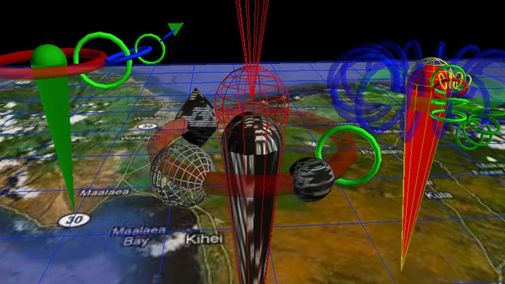
**image of varying topology, geometry, texture, color and transparency.
The scene is composed of a collection of root-pins which may have any number of child-nodes attached in a tree topology. Root pins are independent of each other and can be placed anywhere in the scene. The child-nodes are attached to the parent branch in the tree relative to the parents topo type, position, orientation and scale. The color, scale, geometry and other visual cues are used to represent different parameters of the data set being visualized.
The coordinate system of a node is based on both the nodes topo type and its parents topo type. For example a torus attached to a torus is positioned differently then a pin attached to a torus. However, for most topologies it is the parent topo type that determines the child-nodes coordinate system. Any topo type may be assigned to a node and types can be mixed throughout a tree structure.
In general, child nodes are typically scaled down by 25% or 50% relative to there parent. The main exception is children of pins which are not scaled down. The scale of any node may be changed.
When a parent node changes topo types all of its children are effectively re-mapped into the new coordinates. However the nodes underlying coordinates remain the same, only the graphed position appears differently. The range of different coordinate systems vary, so some re-mapping will wrap the new coordinates. For example an object placed on inside of a torus would have a 'translate_y' (latitude) that is in excess of +/-90 limit of a standard polar system for a sphere. The result is that the node is wrapped around the pole of the sphere and will appear upside down on the backside of the sphere.
order |
field_name |
kml_name |
kml_lo |
kml_hi |
torus_lo |
torus_hi |
1 |
translate_x |
longitude |
-180 |
180 |
-180 |
180 |
2 |
translate_y |
latitude |
-90 |
90 |
-180 |
180 |
3 |
translate_z |
altitude |
0 |
none |
none |
none |
4 |
rotate_y |
heading |
0 |
360 |
0 |
360 |
5 |
rotate_x |
tilt |
0 |
180 |
0 |
180 |
6 |
rotate_z |
roll |
-180 |
180 |
-180 |
180 |
*note that the only difference in KML vs Torus is the latitude range.
Most topologies use the torus limits and allow for latitude of +/- 180 deg. This works well for the a cube which is square or a torus which has an outer side similar to the sphere but with an inner side for which there is no obvious analogy. So any point on a torus can be mapped to a point on the face of a cube and vice versa. However, the range of a sphere only represents half the latitude of most other topo types, hence the sphere wrapping method.
4.1.1 Default Topo - Mixed Tree
The 'default' coordinate system varies depending on the node type and branch level. Root-nodes, cameras and grids default to a Left-Handed Cartesian Coordinate System based on world coordinates. The primary grid is locked to the World Origin (except for scale.) Torus topo is the default for child-nodes of a parent that is topo type default, pin or torus.
4.1.2 Cube Topo - Cubic Tree
The 'cube' topology consists of six independent coordinate systems, one for each facet. Child-nodes are positioned relative to the center of a particular facet and use a Left-Handed Cartesian Coordinate System. Each node has a 'facet' number which keeps track of which side of the parent cube it belongs to. When the node position exceeds the boundaries of a facet it is then automatically re-mapped to the next corresponding facet.
A local facet coordinate system is centered at (0,0). The lower left corner (-X,-Y) is at negative (-180.0, -180.0) deg longitude and latitude, the upper right corner (+X,+Y) is at positive (+180.0, +180.0) deg latitude and longitude. Altitude (+Z) is relative to the cube face and units are the same as the x and y axis, (rather then feet or meters.)
The facet numbers with orientation are compliant with google KML, see the 'cube_facet_map' in the Appendix.
4.1.3 Sphere Topo - Polar Tree
The 'sphere' topology uses polar coordinates that are compatible with the google KML standard. However, the altitude (translate_z) unit length is not the same, the conversion is :
altitude = translate_z / ( earth diameter * 4 * (360/2pi)
or
translate_z = altitude(feet) * 2.00875x10^-10
Longitude, latitude and orientation follow the KML spec for '<model>' at:</model>
http://code.google.com/apis/kml/documentation/kmlreference.html
4.1.4 Torus Topo - Orbital Tree
The 'torus' topology creates an Orbital Tree, similar to the way planets and moons orbit in our solar system, but with an orthogonal twist. That is each sub-orbit is orthogonal to its parents orbit. Unlike the Moon around the Earth and Earth around the Sun which are all roughly in the same plane. The torus orbital tree is similar, except that the moon would be orbiting around the poles instead of the equator.
Multiple children at the same level will have the same orbit orientation, but may have different positions and radius from the parent. The depth of the tree is not limited, (computer resources do impose a practical limit.)
*Future feature - additional topologies to include Polyhedrons, Fractal Tree and nD Tree. nD Tree has an arbitrary number of branches and can be used to represent a variety of dimensional basis. Currently the Sphere topo type can be used to build an nD tree, however it does not impose any special rules which define the particular basis.
4.1.5 Pin Topo - Stacked Tree
The 'pin' topology stacks objects vertically. The root-pins are 5 units high (z in world coordinates,) from the tip to the top, (center of ice-cream sphere.)
Use translate_x to changes height. A value of -180 will place a child object at the tip of the pin, zero is level with the ice-cream sphere and 0-180 will be above the pin.
Offset is 'translate_z' a value of 180 will offset a torus so that its ring intersects the pin.
4.1.6 *nD Tree, Fractal Tree
The 'n' topology is defined by the user. The coordinate system will default to an n-sphere basis where the user specifies 'n' dimensions. Methods are yet to be implemented and help from someone that has a strong background in related mathematics, computer science and/or spatial reasoning would be appreciated. The core concept is to support any type of space with an n-dimensional Neural Physics Engine. The premise is that we do not know how many dimensions exist nor do we know how they operate.
Fractal Tree is a type of nD Tree where the coordinates, distribution and other properties are defined using fractal or chaos based function.
4.2 Geometry
*A variety of geometric types are supported. These range from basic primitives and line graphs to complex fractal geometries, FFTs and custom 3D models. The line graphs can serve as a traditional plot or operate in a realtime oscilloscope fashion.
**image of primitives with texture maps using different colors.
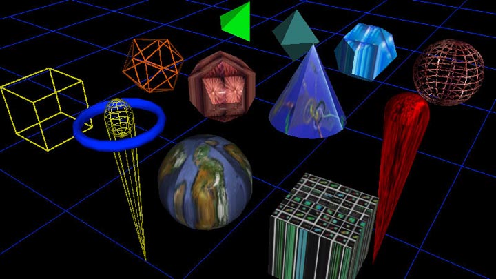
4.2.1 Primitives
The default root pin type looks like an ice-cream cone and typically has at least one torus (ring shape) around it. The default child geometry is a torus. However, both the root-pin and its children can be represented by any number of geometric primitives such as a cone, cube, tetrahedron, sphere, etc... Primitives can be solid or wireframe. For a complete list of primitives please see the 'Geometry Table' in the appendix.
4.2.2 Color & Texture Maps
Optionally, a texture map image can be applied which is effected by the color assigned (including transparency.) For a complete list of geometric primitives see the appendix.
4.2.3 *Points & Lines
*Traditional looking graphs can be generated using Channels to plot lines and/or a series of points. However, these graphs are in 3D, though you can ignore the Z channel to make a 2D plot. Points and Lines graphs are capable of changing with time to create an oscilloscope type graph.
4.2.4 *Surface, FFT
*The surface object is similar to a Points & Lines graph in that it uses channels to map onto the surface of an object. A common example is an FFT surface. Other surface types include a sphere, torus and cylinder. These graphs are generally designed to be updated with time.
4.2.5 *3D Model
*Support for 3DS models, Collada and KML will be added to allow for any type of geometry to be loaded to be used to represent a root pin or child node.
4.3 Grids
There are two types of grids: the primary grid and secondary grids. In addition to the grid lines, a texture map may be applied to the grid.
The primary grid is locked to the origin and cannot be translated or rotated. This provides a fixed global reference point. The primary grid has a default texture map file loaded at application startup, "maps/map00001.jpg" which can be re-assigned at run-time in the same manner as other objects. See 'Commands – Texture Maps' section. The primary grid cannot be deleted but you can 'Hide' it and set the texture ID to zero and it will not be visible.
The grid parameters are modified in a similar manner as other objects and respond to changes in color, hide, scale and texture map assignment. There are some difference in behavior from other objects. Only the grid lines are effected by color and lighting, the texture map is always drawn in full white. Hide will turn off the grid lines, but not the texture map. To hide the texture you must assign it to texture zero which prevents any texture from being drawn. The scale and grid segment commands are specific to the active axes. Vertical stacks are added and subtracted with the grid segment command when the z axis is active, (see 'Command – Active Axes' section.)
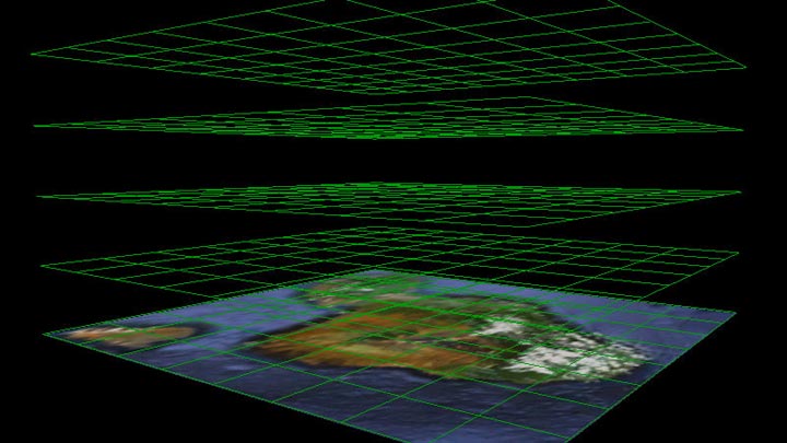
**image of primary grid with a couple of stacks and background texture.
4.4 Lighting
The scene has a pair of white lights designed to provide good front and back shading of objects. They are located in world coordinates at x: -1500, y: 1500, z: -1500 and x: 1500, y: -1500, z: 1500. Standing at the world origin, (center of the grid,) one light is over you right shoulder behind and the other is in front of you down to the left. Generally this will light most objects fairly well, though note that objects moved far from the origin may appear to have different shading.
*Planned update to allow user to specify the number of lights, position and color.
4.5 Cameras
The camera can be flown over the scene using either the keyboard or the mouse. The mouse has several distinct camera translation modes and the keyboard works in a standard flight mode. Also, the camera will auto-center actively chosen objects. By default there are 5 cameras in the scene which with positions stored in the State File. You may create or destroy child cameras, the root-camera is locked and cannot be delted.
Clipping planes are required by OpenGL for efficient 3D rendering. They define the volume in which objects are rendered, any objects outside this volume are clipped and therefore not drawn. You commonly observe this in 3D video games as the point at which distance objects disappear. The default near clipping plane has been set to 1 and far is set to a 1000. So objects more then a 1000 units from the camera (in world coordinates) are clipped, similar for anything closer then 1 unit from the camera.
*Planned update will allow the near and far clip parameters to be set by the user.
4.6 Animation
There are two methods to animate objects in the scene. One is to use [IO_Channels] with Tracks that operate as key frames on position, scale, rotation, color and other parameters. The other is by setting velocity rates which can be loaded from the [ANTz000x.csv] or by using the keyboard.
Keyboard Usage:
First start moving the object using a velocity key, translate keys (W,A,S,D,Q,E) or rotate keys (up, down, right, left arrows). Then while the key is pressed down select another object, for example press 'G' to select the Grid. Now when you release the velocity key the object will keep going, (does not stop.) Using the SHIFT key with a velocity key will increase the rate.
*This 'feature' is a result of a bug... selecting another object while the key is pressed down results in the object never receiving the key-up event that would normally set the velocity back to zero. In the future will be made into an explicit method.
*Physics is currently limited to basic velocity rates, including rotation, and collision with specified boundaries such as the Root Grid floor... significant enhancements are planned.... ranging from Newtonian mechanics to allowing for Relativistic Flight Sim, QED and nD user defined basis.
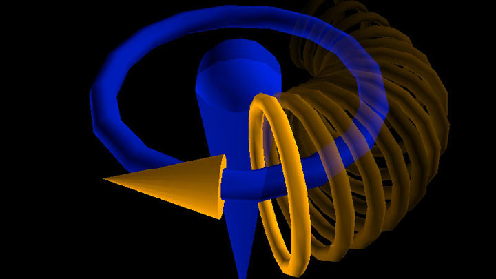
**Torus orbiting parent with translate_rate_x velocity ('A' key).
Related
Wiki: ANTz000x.csv
Wiki: Home
Wiki: IO_Channels
Wiki: User_Manual
