
Menu
▾
▴

What is it ? See yourself http://www.youtube.com/watch?v=26OvsiILrl0

Color test

Device

GUI General
GUI Layout
Home
 Moonbilight
Project Admins:
What is it ? See yourself http://www.youtube.com/watch?v=26OvsiILrl0

Color test

Device
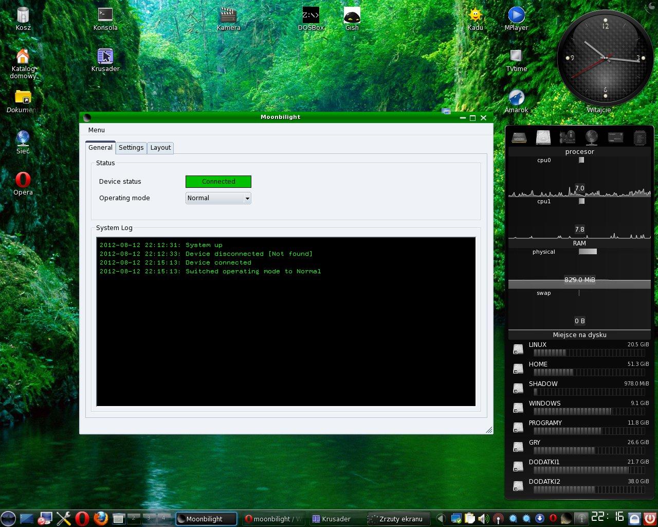
GUI General
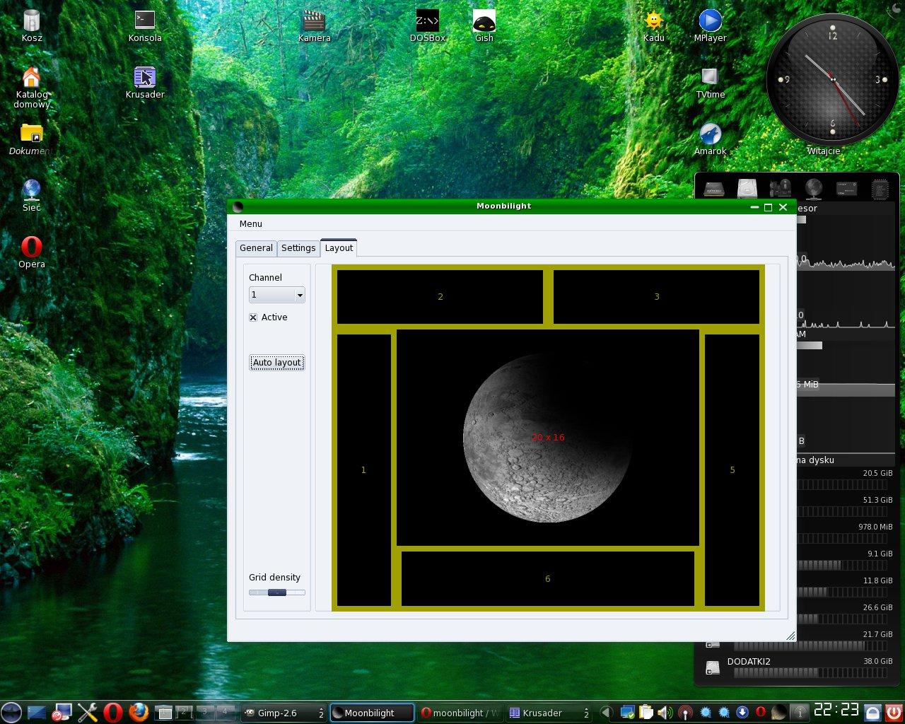
GUI Layout
Moonbilight is an AVR based ambilight for PC.
The project consists of:
- The AVR device and LED panel schematics
- Device firmware
- Controller software; currently supported OS:
- Linux

- Windows

- Linux
Schematics
The core of the device is a ATMega16 / 32 microcontroller clocked by 12 / 16 MHz quartz. There are two independent circuits connected with transistor arrays:
- Microcontroller circuit
- Output circuit
PC communication is done via USB port which is also used to power the microcontroller circuit. The output circuit is powered by external power source (9V power adapter in my case). This is necessary due to USB current limitations but also lets connecting other output devices even with different voltages.
Device firmware
Basically the firmware consists of two elements:
- usb communication via v-usb library (http://www.obdev.at/vusb/)
- led pulse width modulation
The main loop performs operations in order:
- Poll data from USB (if any)
- Increase looped modulation counter (0 - 254)
- Calculate output values from data buffer and modulation counter:
The brightness is determined in 0-255 scale.
The LED is turned on if the counter < led data.
This means that the LED is always off if led value = 0 and always on if led value = 255.
The counter is never less than 0 but always less than 255.
- Synchronize with internal timer
Well, this might seem very odd for you.
I've tried many different ways of the LED pulse width modulation and couldn't get satisfying results. Mainly because of USB architecture and data transfers.
Both USB communication and LED modulation are very sensitive processes.
First of all USB has small timing tolerance, so the communication process cannot be interrupted.
Secondly LED modulation shouldn't be interrupted or the LEDs will blink.When I've used a simple loop with usbPoll and LED modulation algorithm, the spontaneous data transfers caused different intervals between modulation steps which of course manifested itself by blinking.
Then I've tried placing modulation in the interrupt routine, but setting too small frequency have caused blinking and setting too high frequency have caused interferences in usb communication.
Next I decided to use the timer not for interrupt but only as a counter for LED modulation. Alas this algorithm have caused "loosing" counter values which of course caused blinking (well mainly for smaller brightness).
Finally I decided to use the timer to synchronize main loop. I know this is ugly solution but it gives the best results. The blinking still occurs (for small values) but it is not as annoying as when the other methods were used.
- Set values to output ports
No big deal here. Just set corresponding calculated values to the output pins.
Controller software
Since the device uses HID interface, the host controller doesn't need any drivers to be installed. They should already be included in the OS. Also V-USB comes with some nice examples, so the implementation is very easy.
As a matter of fact, any program that can send appropriate data through USB port can be used to control the device. This facilitates hardware testing before having to write any GUI (That's why the software is still incomplete).
The application user interface is written using QT library (http://qt-project.org/). It is split into sections:
- General
device status indicator (ie. device connected, IO error)
operating mode combo (ie. normal, demo)
custom operating mode (for custom plugins)
plugin list (for activating/deactivating plugins)
system log
- Settings
screen geometry
color adjustment (intensity, gamma)
control panel (update interval)
- Layout
switching channels on/off
selecting data source area for each channel
Normally, the data are sent to the device at 100ms intervals. Maybe there will be a slider to adjust this speed in the future, but for now I got best results with this speed (the more data, the more interferences, see above).
When there is no data transfer (the idle mode is set or the device is disconnected), the software checks for device presence at 2s intervals.
Available operating modes:
- idle (nothing is sent to the device)
- normal (the data are computed using current settings)
- demo (the data source is a programmable sequence repeated in a loop)
- test (the white color processed by settings; the main purpose is a color calibration)
- custom (for plugin data sources)
Plugins
The GUI software gives the ability to extend its functionality by providing a plugin API.
The currently available plugin functionality:
- adding additional data sources (including sequences like demo mode)
- adding tabs to GUI for configuration, display or any other purposes
- reading configuration and controlling operating mode (It's ugly and might be modified in future)
What are these plugins for at all ?
- Well, first of all, the program is smaller without unnecessary features - lighter is better, trust me.
- Secondly, it is possible to add platform dependent features. I would like to make a DirectX support in the future (yes, the full screen DX applications aren't supported for now). Alas, it isn't an easy task (at least for me), so I can't promise to make it.
- Finally, anyone can extend the functionality by writing their own plugins, so the software is not limited to its basic functionality.
The plugin API and some example plugins can be found in the gui/.moonplugs/ directory.
See gui/.moonplugs/test/plugin_api.txt for details.
Note: Since the AudioGlow plugin is based on ALSA it will only work on Linux. Sorry for that inconvenience but I couldn't make QtMultimedia work.
