MatrixPilot Wiki
Brought to you by:
inspirati

The MatrixPilot OSD is meant to help FPV flyers by giving them some useful instrumentation inside their video cockpits. It overlays useful values (altitude, distance to home, direction to home, speed, battery stats, etc) on top of your live video stream. It's very configurable, so you can set it up to show you just the information you want, where you want it. Above is an example.
Many OSD options exist for FPV flyers. But if you're already using MatrixPilot running on an onboard UDB, then this is the smallest, lightest, cheapest OSD solution you can add to your system. It may also be the most accurate and responsive hobby OSD available, since it is driven by MatrixPilot's dead-reckoning IMU.
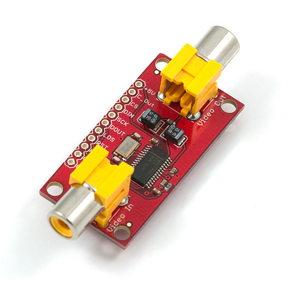
The downside is that there is no simple plug-and-play hardware to add on. You have to buy a breakout board from SparkFun, do a bit of desoldering and soldering, and then add some shielding around it when you're done. But this is easier than it may sound, since the breakout board does its job, and lets you do only easy through-hole soldering.
1 Breakout Board for MAX7456 On Screen Display from SparkFun
2 24" M-F thin/light servo-extensions
1 12" M-F thin/light servo-extension
2 0.5" toroids like this one
2 2" lengths of 1-inch diameter heat-shrink tubing
1 2"x3" chunk of conductive shielding fabric, or enough copper tape to wrap the board.
Step 1 is to de-solder the RCA jacks from the breakout board. Besides being first, this step is also the hardest. It starts out looking like this:
After you've done that, the complete set of ingredients should look about like this: (except that I started with all 12" cables instead of using 2 24" cables like I should have...)

Take the 12" cable and separate the 3 wires from each other, but only right near the middle of the cable, then clip the black and orange wires, but leave the red one intact, like this:

Now we'll strip about 1/8" from the ends of each of these 4 open wires, and solder them to the board. For the ends connected to the sheathed end of the cable, connect black to the hole right by the word "In" of "Video In", and orange to the other desoldered hole on that end of the board, near the word GND. (You can add wrap this end of the cable through a toroid about 5 times if you need to clean up interference from a noisy camera. If you're doing this, you may want to leave more cable on this end than the other end, to have enough length to wrap through the toroid.) For the other end of the cable, connect orange to the hole near the "V" in "Video Out", and the black to the other desoldered hole near the +5V, like this:

Cut the sheathed ends off of the 2 24" cables. For each cable, pull the 3 wires apart so they're individual strands. For one of the cables, remove the orange wire, leaving just red and black.

Then wrap both cables (all 5 wires) through the toroid. One cable at a time is easier. Make sure to get at least about 5 wraps of each through the toroid. This should stop the noise from your video TX from being conducted through these wires back to the UDB. Leave about 2-3 inches of cable past the toroid, like this:

Now connect the red and black wires from the 2-wire cable to the +5V and GND pins, like this:

And the black, red, and orange wires from the 3-wire cable to CS, SCK, DIN as seen here: (note that the 3 holes are not in the same order as the 3 wires)

Then add a small wire jumper connecting RST directly to +5V as seen here:

And connect another small wire to any ground pin, and leave the other end hanging for now. We'll connect this to the shielding later. (This is a good time to test that the OSD works. Testing info below.) Now it's time to heat shrink one layer of tubing around the board.

Now wrap a layer of shielding around the board. We're trying to stop the noise radiated by the MAX7456 from interfering with the video or UDB. You can use some electrical tape to hold it together while you solder the other end of the ground wire to the shielding. Using a drop of solder flux makes this step easy.

Now heat shrink the 2nd tube around the shielding.

This step is optional, but I think it can help with RFI problems: braid the 3-wire cable pretty tightly, and twist the 2-wire cable tightly, so you end up with cables looking like this:

Installation of your beautiful new OSD board is easy. The 2 long wires go to the UDB. Plug the 2-wire cable into power and ground of a spare ServoOut or RadioIn channel. (Or anywhere you can easily grab 5V and Ground.) On the UDB2/3, the 3-wire cable connects to RE0-RE2-RE4 with black on RE0. On the UDB4, the 3-wire cable connects to the SPI1 port DI1-DO1-CK1 with black wire on DI1.
The other 2 cables are video in and out, which go to your camera and TX.
To test it out, first make sure there are no shorts in your solder work.
Then connect it all up, and program the FlashOSD program (in the Tools directory of the MatrixPilot Download) onto your UDB, and let it run while watching the video. If you end up with a huge grid of letters, numbers, and symbols, then it works!
Running the FlashOSD program is a necessary step, since it updates the Font stored on the OSD, that MatrixPilot uses to display data. After performing this step, you'll have to install MatrixPilot back onto your UDB before you fly.
To configure the OSD layout to your liking, first enable the OSD by setting USE_OSD to 1 in options.h. Then edit the osd_layout.h file to decide which values you want to see, and where. Note that to see battery stats, or RSSI values, you'll have to enable and set up Analog Inputs.
// OSD_VIDEO_FORMAT can be set to either OSD_NTSC, or OSD_PAL
#define OSD_VIDEO_FORMAT        OSD_NTSC

// The callsign is written using characters from the OSD Font file.  (See Tools/FlashOSD/.)
// This has to end with 0xFF.
// Adjust the placement using OSD_LOC_CALLSIGN_HORIZ and OSD_LOC_CALLSIGN_VERT.
#define OSD_CALL_SIGN           {0x95, 0x81, 0x82, 0x83, 0x84, 0x85, 0xFF} // K12345

#define OSD_SHOW_CENTER_DOT     0

#define OSD_SHOW_HORIZON        0
#define OSD_HORIZON_WIDTH       10
#define OSD_HORIZON_ROLL_REVERSED   0
#define OSD_HORIZON_PITCH_REVERSED  0

#define OSD_AUTO_HIDE_GPS       1           // Only show Lat, Long, and Num Sats while slow and low.


// OSD Element Locations
// Set each one to OSD_LOC_DISABLED or OSD_LOC(row, col) from (0, 0) to (12, 29) for NTSC or up to (15, 29) for PAL.

#define OSD_LOC_DIST_TO_GOAL        OSD_LOC(1, 13)      // 5 characters wide
#define OSD_LOC_ARROW_TO_GOAL       OSD_LOC(2, 14)      // 2 characters wide

#define OSD_LOC_AP_MODE         OSD_LOC(1, 20)      // 1 character wide

#define OSD_LOC_ALTITUDE        OSD_LOC(1, 4)       // 6 characters wide
#define OSD_LOC_VARIO_NUM       OSD_LOC_DISABLED    // 4 characters wide
#define OSD_LOC_VARIO_ARROW     OSD_LOC(1, 11)      // 1 character wide
#define OSD_LOC_VERTICAL_ANGLE_HOME OSD_LOC_DISABLED    // 4 characters wide

#define OSD_LOC_AIR_SPEED_M_S       OSD_LOC_DISABLED    // 4 characters wide
#define OSD_LOC_AIR_SPEED_MI_HR     OSD_LOC(1, 22)      // 4 characters wide
#define OSD_LOC_AIR_SPEED_KM_HR     OSD_LOC_DISABLED    // 4 characters wide

#define OSD_LOC_GROUND_SPEED_M_S    OSD_LOC_DISABLED    // 4 characters wide
#define OSD_LOC_GROUND_SPEED_MI_HR  OSD_LOC_DISABLED    // 4 characters wide
#define OSD_LOC_GROUND_SPEED_KM_HR  OSD_LOC_DISABLED    // 4 characters wide

#define OSD_LOC_HEADING_NUM     OSD_LOC_DISABLED    // 5 characters wide
#define OSD_LOC_HEADING_CARDINAL    OSD_LOC_DISABLED    // 3 characters wide

#define OSD_LOC_VERTICAL_ACCEL      OSD_LOC_DISABLED    // 3 characters wide
#define OSD_LOC_VERTICAL_WIND_SPEED OSD_LOC_DISABLED    // 4 characters wide
#define OSD_LOC_TOTAL_ENERGY        OSD_LOC_DISABLED    // 4 characters wide

#define OSD_LOC_ROLL_RATE       OSD_LOC_DISABLED    // 3 characters wide
#define OSD_LOC_PITCH_RATE      OSD_LOC_DISABLED    // 3 characters wide
#define OSD_LOC_YAW_RATE        OSD_LOC_DISABLED    // 3 characters wide

#define OSD_LOC_NUM_SATS        OSD_LOC(12, 3)      // 4 characters wide
#define OSD_LOC_GPS_LAT         OSD_LOC(12, 7)      // 9 characters wide
#define OSD_LOC_GPS_LONG        OSD_LOC(12, 17)     // 10 characters wide

#define OSD_LOC_CALLSIGN_HORIZ      OSD_LOC_DISABLED    // variable width
#define OSD_LOC_CALLSIGN_VERT       OSD_LOC(0,28)       // variable height

#define OSD_LOC_CPU_LOAD        OSD_LOC_DISABLED    // 5 characters wide

#define OSD_LOC_BATT_CURRENT        OSD_LOC(2,17)       // 4 characters wide
#define OSD_LOC_BATT_USED       OSD_LOC(2,22)       // 5 characters wide
#define OSD_LOC_BATT_VOLTAGE        OSD_LOC(3,17)       // 4 characters wide

#define OSD_LOC_RSSI            OSD_LOC(3,23)       // 4 characters wide}}}
Wiki: CompatibleHardware
Wiki: HowToConfigure
Wiki: HowToConfigureMP30
Wiki: HowToConfigureMP33
Wiki: HowToInstall
Wiki: MatrixPilot
