MatrixPilot Wiki
Brought to you by:
inspirati
The UDB3 boards only include built in connections for 4 Radio Input channels, and 3 Servo Output channels.
Here's how to connect the 5th Input channel, and the 4th, 5th, and 6th Output channels for a UDB4. If you have a UDB4 then you do not need to know this, as the UDB4 has 8 inputs and 8 outputs as standard. Also note that as of MatrixPilot 3.0, it is also possible to use a PPM Encoder board to allow up to 8 RC inputs to come into the UDB 3 through one servo cable attached to IN4. This leaves you with up to 6 proper output servo connectors (by using In1-In3 as additional outputs) plus the 3 extra servo outputs described here.
The new Input runs on pin RE8. The new outputs on RE0, RE2, and RE4. This pins are made available along the bottom-left edge of the board.
If you just need one more input and one more output, here's a simple way to do it:

To use all of these pins as a radio input and servo outputs, here's what I suggest doing:
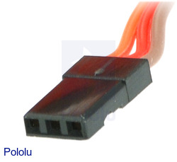
(1) Note: I'm calling the below pictured connector female. This is the end that usually comes attached to servos, and that usually plugs into a receiver.
An easier method is to use these cables from pololu.com:
http://www.pololu.com/catalog/product/1800
http://www.pololu.com/catalog/product/1801
http://www.pololu.com/catalog/product/1902
http://www.pololu.com/catalog/product/1903
and arrange them as seen in these photos showing the parts needed to add one extra input and two extra outputs, both before:

and after connecting them together:

The 4 black connectors at the bottom of the photo just above are, left to right, servo output 5, servo output 4, a connection to a spare receiver output for power, and radio input 5.
No soldering is required to build these cables, although you'll still have to solder the header pins onto the UDB.
Now to use these cables, connect the new Input 5 to a channel you want to use on your receiver. And attach the other two female ends to 2 unused channels on your receiver. (You can connect one of them to the BATT connection on the receiver, if that is unused in your setup.) Note that these two channels are only being used for power, and the values from the receiver on these channels is being ignored. Now you can connect servos to the other ends of these cables, and they will be driven as output channels 4, 5, and 6.
Here's a diagram put together by Peter Hollands:
Wiki: CompatibleHardware
Wiki: HowToConfigure
Wiki: HowToConfigureMP20
Wiki: HowToConfigureMP25
Wiki: HowToConfigureMP30
Wiki: HowToConfigureMP33
Wiki: HowToInstall
Wiki: HowToInstallMP25
Wiki: MatrixPilot
Wiki: MatrixPilotMP25
Wiki: MatrixPilotMP33
Wiki: SidebarMP25

View and moderate all "wiki Discussion" comments posted by this user
Mark all as spam, and block user from posting to "Wiki"
Originally posted by: analogue... (code.google.com)@gmail.com
Note that the "orange" signal wires described here are actually more often white.
View and moderate all "wiki Discussion" comments posted by this user
Mark all as spam, and block user from posting to "Wiki"
Originally posted by: joe.co... (code.google.com)@gmail.com
Can you please clarify, in the diagram above, what is the "330 Ohm"? Do I need Resisters put in there?
Cheers
View and moderate all "wiki Discussion" comments posted by this user
Mark all as spam, and block user from posting to "Wiki"
Originally posted by: analogue... (code.google.com)@gmail.com
is there any explanation for the "330 Ohm" mentions in the lower diagram? Are we supposed to be soldering in resistors or something? Mystifying...
View and moderate all "wiki Discussion" comments posted by this user
Mark all as spam, and block user from posting to "Wiki"
Originally posted by: benjie
The resistors are optional. Probably a good idea, but they don't seem necessary.
View and moderate all "wiki Discussion" comments posted by this user
Mark all as spam, and block user from posting to "Wiki"
Originally posted by: parv... (code.google.com)@gmail.com
In the board manual says "Finally, note that all spare pins are directly connected, without any series resistors, so be careful." So, the resistors are necessary or not?
View and moderate all "wiki Discussion" comments posted by this user
Mark all as spam, and block user from posting to "Wiki"
Originally posted by: syedali.... (code.google.com)@gmail.com
hi benjie. if i add an extra servo output, do i have to change the program? to send the specific pwm signals to the extra servo? thanks.