Menu
▾
▴
[Linuxptp-devel] Optimal P, I constants
|
From: Miroslav L. <mli...@re...> - 2013-04-23 13:45:22
|
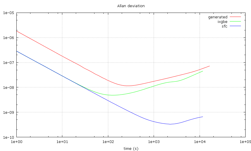
I've been experimenting with phc2sys and the clknetsim simulator to find out how is the clock synchronization affected by changes in the P, I constants with different jitters and clock stabilities, and I thought others on this list might be interested in the results. The instability of the clock frequency is called wander and it is described by random-walk noise. A good value used to simulate an average computer clock is around 0.5 ppb/s. However, there are non-random effects like changes in the temperature due to variations in the CPU load etc, which may quickly change the frequency by several ppm. These effects are difficult to describe, so I simply use a larger wander (up to 10 ppb/s) to make a room for them. In some older experiments with NTP, when compared to results obtained on real HW, this worked pretty well. I'm also interested in how stable are the PTP clocks to allow better configuration of the ptp4l servo. I've measured the Allan deviation with two different NICs. One seems to have an ordinary oscillator (wander slightly below 1 ppb/s), the other seems to have some kind of stabilization (wander around 0.01 ppb/s). Here is a plot of the two measured deviations and a simulation with 1us jitter and 1ppb/s wander for comparison: http://mlichvar.fedorapeople.org/tmp/ptp_adev.png The time interval in the Allan deviation plot where the -1 jitter slope intersects the +1/2 wander slope is called Allan intercept. It is a ratio of the jitter and wander. The results of the servo tests are presented here in maps. I tried 3D plots, but it wasn't very readable. The X axis is the P constant in log10, the Y axis is the I constant in log10 and the Z axis is the measured RMS time error of the simulated clock in decibels relative to the lowest (best) value in the map. Please note that the absolute values of jitter and wander are not really important here, only their ratio - Allan intercept. First is a map done with 10ns normally distributed jitter, 10ppb/s wander and 1s update interval. It looks like this is the case the current phc2sys default P, I (0.7, 0.3) are optimized for. -4.0 -3.7 -3.3 -3.0 -2.7 -2.3 -2.0 -1.7 -1.3 -1.0 -0.7 -0.3 +0.0 -5.0 42 39 37 36 35 33 31 30 27 27 26 22 19 -4.7 40 38 36 34 33 31 30 28 26 25 24 22 19 -4.3 39 35 35 33 32 30 28 26 24 23 21 18 18 -4.0 37 34 33 31 30 28 27 25 23 22 20 18 16 -3.7 34 33 31 30 28 26 25 23 21 20 17 16 15 -3.3 34 31 29 27 26 24 23 21 20 18 16 14 13 -3.0 31 29 29 26 24 23 21 20 18 16 15 13 11 -2.7 31 27 27 25 24 21 20 18 16 15 13 11 10 -2.3 29 27 25 23 21 20 18 16 15 13 11 10 8 -2.0 27 24 23 21 20 18 16 15 13 11 10 8 6 -1.7 24 22 21 19 18 16 15 13 11 10 8 6 5 -1.3 22 21 19 18 17 14 13 11 10 8 6 5 3 -1.0 22 19 18 16 15 13 11 10 8 6 5 3 2 -0.7 18 18 17 14 13 11 10 8 6 5 3 2 0 -0.3 18 17 15 12 12 10 9 7 5 4 2 1 0 +0.0 18 16 14 13 12 10 8 7 5 3 2 1 1 This one is with 100us jitter, 10ppb/s wander and 1s interval. The best I constant now becomes impractical as it will take hours for the servo to converge. -4.0 -3.7 -3.3 -3.0 -2.7 -2.3 -2.0 -1.7 -1.3 -1.0 -0.7 -0.3 +0.0 -5.0 15 12 10 8 6 4 3 2 2 3 5 7 9 -4.7 11 10 9 6 4 3 2 1 1 3 5 6 9 -4.3 9 8 6 5 3 2 1 0 1 3 5 6 9 -4.0 7 7 6 4 3 1 0 0 1 3 5 6 9 -3.7 10 9 6 4 3 2 1 0 1 3 5 6 9 -3.3 10 8 8 6 4 3 1 1 2 3 5 6 9 -3.0 12 11 9 8 6 5 3 2 2 3 5 6 9 -2.7 15 13 11 9 7 6 5 3 3 3 5 6 9 -2.3 16 13 13 11 10 8 6 5 4 4 5 6 9 -2.0 17 17 15 12 11 9 8 6 5 4 5 7 9 -1.7 20 17 16 15 13 11 10 8 6 5 5 7 9 -1.3 19 18 18 16 14 13 11 9 8 7 6 7 9 -1.0 18 18 18 17 16 15 13 11 10 8 7 7 9 -0.7 16 16 16 16 16 15 14 13 11 10 9 8 9 -0.3 15 15 15 14 14 14 14 14 13 11 10 10 10 +0.0 13 13 13 13 13 13 13 13 13 12 12 11 11 To see how the results change with different update intervals, these three are with 10ns jitter, 1ppb/s wander, and 100s, 1s and 0.01s update intervals respectively. The sudden jump to 45-47 shows where the servo becomes unstable. -3.0 -2.7 -2.3 -2.0 -1.7 -1.3 -1.0 -0.7 -0.3 +0.0 +0.3 +0.7 +1.0 -3.0 10 9 7 5 46 46 46 46 45 45 45 45 45 -2.7 9 7 5 3 46 46 46 46 46 45 45 45 45 -2.3 7 5 3 2 46 46 46 46 46 46 45 45 45 -2.0 5 3 2 0 46 46 46 46 46 45 45 45 45 -1.7 3 2 0 46 46 46 46 46 45 46 45 45 45 -1.3 46 46 46 46 46 46 46 46 46 45 45 45 45 -1.0 46 46 46 46 46 46 46 46 46 46 45 45 45 -0.7 46 46 46 46 45 46 46 46 45 46 45 45 45 -0.3 46 46 46 46 45 46 45 46 45 45 45 45 45 +0.0 45 46 46 46 46 46 45 45 45 45 45 45 45 -3.0 -2.7 -2.3 -2.0 -1.7 -1.3 -1.0 -0.7 -0.3 +0.0 +0.3 +0.7 +1.0 -3.0 19 18 16 15 13 11 10 9 7 4 46 46 46 -2.7 19 16 15 13 12 10 8 7 5 4 47 46 46 -2.3 18 14 13 11 10 8 6 5 4 3 47 47 46 -2.0 15 14 12 10 8 6 5 3 2 2 47 47 47 -1.7 14 11 10 8 6 5 3 2 1 2 47 47 47 -1.3 13 10 8 6 5 3 2 1 0 2 47 47 47 -1.0 10 11 8 6 5 3 2 0 0 2 47 47 47 -0.7 11 11 8 7 5 4 2 1 1 2 47 47 47 -0.3 13 11 10 9 7 5 4 2 2 3 47 47 47 +0.0 15 14 13 10 9 7 6 4 4 5 47 47 47 -3.0 -2.7 -2.3 -2.0 -1.7 -1.3 -1.0 -0.7 -0.3 +0.0 +0.3 +0.7 +1.0 -3.0 36 35 28 31 23 23 10 7 6 2 1 14 15 -2.7 31 35 27 30 10 21 7 4 3 2 1 1 9 -2.3 28 31 24 31 23 16 7 4 2 1 1 2 2 -2.0 21 29 29 25 21 7 5 3 2 1 0 2 3 -1.7 26 28 27 26 18 15 4 4 2 1 1 1 4 -1.3 21 18 29 26 12 13 9 4 3 2 1 2 3 -1.0 27 23 23 21 14 10 9 5 4 4 2 2 4 -0.7 19 18 25 21 13 14 9 8 6 5 3 3 4 -0.3 22 21 12 20 17 12 12 9 9 6 5 4 4 +0.0 20 17 14 16 13 15 12 11 9 8 6 5 5 More data and the script which was used to generate it is available here: http://mlichvar.fedorapeople.org/clknetsim/ptp/pi_search/ I was wondering how useful it would be to have a new servo parameter for the Allan intercept and set the P, I constants automatically according the intercept and measured clock update interval. What do you think? -- Miroslav Lichvar |