Thread: [Linuxptp-devel] Optimal P, I constants
PTP IEEE 1588 stack for Linux
Brought to you by:
rcochran
|
From: Miroslav L. <mli...@re...> - 2013-04-23 13:45:22
|
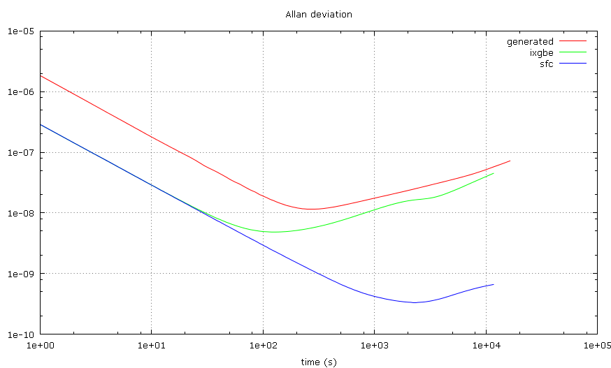
I've been experimenting with phc2sys and the clknetsim simulator to find out how is the clock synchronization affected by changes in the P, I constants with different jitters and clock stabilities, and I thought others on this list might be interested in the results. The instability of the clock frequency is called wander and it is described by random-walk noise. A good value used to simulate an average computer clock is around 0.5 ppb/s. However, there are non-random effects like changes in the temperature due to variations in the CPU load etc, which may quickly change the frequency by several ppm. These effects are difficult to describe, so I simply use a larger wander (up to 10 ppb/s) to make a room for them. In some older experiments with NTP, when compared to results obtained on real HW, this worked pretty well. I'm also interested in how stable are the PTP clocks to allow better configuration of the ptp4l servo. I've measured the Allan deviation with two different NICs. One seems to have an ordinary oscillator (wander slightly below 1 ppb/s), the other seems to have some kind of stabilization (wander around 0.01 ppb/s). Here is a plot of the two measured deviations and a simulation with 1us jitter and 1ppb/s wander for comparison: http://mlichvar.fedorapeople.org/tmp/ptp_adev.png The time interval in the Allan deviation plot where the -1 jitter slope intersects the +1/2 wander slope is called Allan intercept. It is a ratio of the jitter and wander. The results of the servo tests are presented here in maps. I tried 3D plots, but it wasn't very readable. The X axis is the P constant in log10, the Y axis is the I constant in log10 and the Z axis is the measured RMS time error of the simulated clock in decibels relative to the lowest (best) value in the map. Please note that the absolute values of jitter and wander are not really important here, only their ratio - Allan intercept. First is a map done with 10ns normally distributed jitter, 10ppb/s wander and 1s update interval. It looks like this is the case the current phc2sys default P, I (0.7, 0.3) are optimized for. -4.0 -3.7 -3.3 -3.0 -2.7 -2.3 -2.0 -1.7 -1.3 -1.0 -0.7 -0.3 +0.0 -5.0 42 39 37 36 35 33 31 30 27 27 26 22 19 -4.7 40 38 36 34 33 31 30 28 26 25 24 22 19 -4.3 39 35 35 33 32 30 28 26 24 23 21 18 18 -4.0 37 34 33 31 30 28 27 25 23 22 20 18 16 -3.7 34 33 31 30 28 26 25 23 21 20 17 16 15 -3.3 34 31 29 27 26 24 23 21 20 18 16 14 13 -3.0 31 29 29 26 24 23 21 20 18 16 15 13 11 -2.7 31 27 27 25 24 21 20 18 16 15 13 11 10 -2.3 29 27 25 23 21 20 18 16 15 13 11 10 8 -2.0 27 24 23 21 20 18 16 15 13 11 10 8 6 -1.7 24 22 21 19 18 16 15 13 11 10 8 6 5 -1.3 22 21 19 18 17 14 13 11 10 8 6 5 3 -1.0 22 19 18 16 15 13 11 10 8 6 5 3 2 -0.7 18 18 17 14 13 11 10 8 6 5 3 2 0 -0.3 18 17 15 12 12 10 9 7 5 4 2 1 0 +0.0 18 16 14 13 12 10 8 7 5 3 2 1 1 This one is with 100us jitter, 10ppb/s wander and 1s interval. The best I constant now becomes impractical as it will take hours for the servo to converge. -4.0 -3.7 -3.3 -3.0 -2.7 -2.3 -2.0 -1.7 -1.3 -1.0 -0.7 -0.3 +0.0 -5.0 15 12 10 8 6 4 3 2 2 3 5 7 9 -4.7 11 10 9 6 4 3 2 1 1 3 5 6 9 -4.3 9 8 6 5 3 2 1 0 1 3 5 6 9 -4.0 7 7 6 4 3 1 0 0 1 3 5 6 9 -3.7 10 9 6 4 3 2 1 0 1 3 5 6 9 -3.3 10 8 8 6 4 3 1 1 2 3 5 6 9 -3.0 12 11 9 8 6 5 3 2 2 3 5 6 9 -2.7 15 13 11 9 7 6 5 3 3 3 5 6 9 -2.3 16 13 13 11 10 8 6 5 4 4 5 6 9 -2.0 17 17 15 12 11 9 8 6 5 4 5 7 9 -1.7 20 17 16 15 13 11 10 8 6 5 5 7 9 -1.3 19 18 18 16 14 13 11 9 8 7 6 7 9 -1.0 18 18 18 17 16 15 13 11 10 8 7 7 9 -0.7 16 16 16 16 16 15 14 13 11 10 9 8 9 -0.3 15 15 15 14 14 14 14 14 13 11 10 10 10 +0.0 13 13 13 13 13 13 13 13 13 12 12 11 11 To see how the results change with different update intervals, these three are with 10ns jitter, 1ppb/s wander, and 100s, 1s and 0.01s update intervals respectively. The sudden jump to 45-47 shows where the servo becomes unstable. -3.0 -2.7 -2.3 -2.0 -1.7 -1.3 -1.0 -0.7 -0.3 +0.0 +0.3 +0.7 +1.0 -3.0 10 9 7 5 46 46 46 46 45 45 45 45 45 -2.7 9 7 5 3 46 46 46 46 46 45 45 45 45 -2.3 7 5 3 2 46 46 46 46 46 46 45 45 45 -2.0 5 3 2 0 46 46 46 46 46 45 45 45 45 -1.7 3 2 0 46 46 46 46 46 45 46 45 45 45 -1.3 46 46 46 46 46 46 46 46 46 45 45 45 45 -1.0 46 46 46 46 46 46 46 46 46 46 45 45 45 -0.7 46 46 46 46 45 46 46 46 45 46 45 45 45 -0.3 46 46 46 46 45 46 45 46 45 45 45 45 45 +0.0 45 46 46 46 46 46 45 45 45 45 45 45 45 -3.0 -2.7 -2.3 -2.0 -1.7 -1.3 -1.0 -0.7 -0.3 +0.0 +0.3 +0.7 +1.0 -3.0 19 18 16 15 13 11 10 9 7 4 46 46 46 -2.7 19 16 15 13 12 10 8 7 5 4 47 46 46 -2.3 18 14 13 11 10 8 6 5 4 3 47 47 46 -2.0 15 14 12 10 8 6 5 3 2 2 47 47 47 -1.7 14 11 10 8 6 5 3 2 1 2 47 47 47 -1.3 13 10 8 6 5 3 2 1 0 2 47 47 47 -1.0 10 11 8 6 5 3 2 0 0 2 47 47 47 -0.7 11 11 8 7 5 4 2 1 1 2 47 47 47 -0.3 13 11 10 9 7 5 4 2 2 3 47 47 47 +0.0 15 14 13 10 9 7 6 4 4 5 47 47 47 -3.0 -2.7 -2.3 -2.0 -1.7 -1.3 -1.0 -0.7 -0.3 +0.0 +0.3 +0.7 +1.0 -3.0 36 35 28 31 23 23 10 7 6 2 1 14 15 -2.7 31 35 27 30 10 21 7 4 3 2 1 1 9 -2.3 28 31 24 31 23 16 7 4 2 1 1 2 2 -2.0 21 29 29 25 21 7 5 3 2 1 0 2 3 -1.7 26 28 27 26 18 15 4 4 2 1 1 1 4 -1.3 21 18 29 26 12 13 9 4 3 2 1 2 3 -1.0 27 23 23 21 14 10 9 5 4 4 2 2 4 -0.7 19 18 25 21 13 14 9 8 6 5 3 3 4 -0.3 22 21 12 20 17 12 12 9 9 6 5 4 4 +0.0 20 17 14 16 13 15 12 11 9 8 6 5 5 More data and the script which was used to generate it is available here: http://mlichvar.fedorapeople.org/clknetsim/ptp/pi_search/ I was wondering how useful it would be to have a new servo parameter for the Allan intercept and set the P, I constants automatically according the intercept and measured clock update interval. What do you think? -- Miroslav Lichvar |
|
From: Keller, J. E <jac...@in...> - 2013-04-23 18:43:39
|
> -----Original Message----- > From: Miroslav Lichvar [mailto:mli...@re...] > Sent: Tuesday, April 23, 2013 6:45 AM > To: lin...@li... > Subject: [Linuxptp-devel] Optimal P, I constants > > I've been experimenting with phc2sys and the clknetsim simulator to > find out how is the clock synchronization affected by changes in the > P, I constants with different jitters and clock stabilities, and I > thought others on this list might be interested in the results. <snip> > More data and the script which was used to generate it is available > here: > http://mlichvar.fedorapeople.org/clknetsim/ptp/pi_search/ > > I was wondering how useful it would be to have a new servo parameter > for the Allan intercept and set the P, I constants automatically > according the intercept and measured clock update interval. What do > you think? > > -- > Miroslav Lichvar > Hey Miroslav - First of all, thank you for the detail, this is an impressive in depth look at the P/I servos. I think it might be better (at first) to create a new clock which is based on Allan intercept, since most people doing PTP are familiar enough with the P/I constants servo. I do think in the long term it definitely makes more sense to put the Allan intercept, as that appears to work better, and is easier to measure if I am not mistaken? (Jitter * wander in pbb, right?) Wouldn't this also have to set the update frequency as well? It appears that some update frequencies cause the result to be unstable or too slow.. Thanks - Jake |
|
From: Miroslav L. <mli...@re...> - 2013-04-24 09:34:55
|
On Tue, Apr 23, 2013 at 06:42:10PM +0000, Keller, Jacob E wrote: > I think it might be better (at first) to create a new clock which is based on Allan intercept, since most people doing PTP are familiar enough with the P/I constants servo. I think the options to set P, I directly could be still used, the new option would be effective only if the configured P or I was zero, or the new option was non-zero. > I do think in the long term it definitely makes more sense to put the Allan intercept, as that appears to work better, and is easier to measure if I am not mistaken? (Jitter * wander in pbb, right?) The Allan intercept is approximately (jitter / wander_per_second)^(2/3) * 2 The deviation can be calculated from offsets reported by phc2sys (or ptp4l) when free running and the intercept can be estimated from the plot. A tool I use is at https://github.com/mlichvar/ppsallan. With phc2sys it can be used like this: phc2sys -P 1e-50 -I 1e-50 -m | tail -n +10 > log awk '{ printf "%.9f\n", $4 * 1e-9 }' < log | ppsallan -B > adev plotallan adev The offsets should be collected at one second interval, or the result needs to be scaled accordingly. To see the +1/2 slope well, it's good to have at least 10 hours or more of data. > Wouldn't this also have to set the update frequency as well? It appears that some update frequencies cause the result to be unstable or too slow.. Yes, the update interval would need to be included in the P, I calculation. I think that's the main problem with the current code, that the sync interval can change to a longer one in the runtime, but P, I don't change and the servo may suddenly be unstable. Ideally, the constants would be adjusted automatically according to the current conditions. Or try a more sophisticated servo. I have some ideas I want to explore, but it's not on my short-term todo list. Thanks, -- Miroslav Lichvar |
|
From: Keller, J. E <jac...@in...> - 2013-04-24 18:11:17
|
> -----Original Message----- > From: Miroslav Lichvar [mailto:mli...@re...] > Sent: Wednesday, April 24, 2013 2:35 AM > To: Keller, Jacob E > Cc: lin...@li... > Subject: Re: [Linuxptp-devel] Optimal P, I constants > > On Tue, Apr 23, 2013 at 06:42:10PM +0000, Keller, Jacob E wrote: > > I think it might be better (at first) to create a new clock which is based > on Allan intercept, since most people doing PTP are familiar enough > with the P/I constants servo. > > I think the options to set P, I directly could be still used, the new > option would be effective only if the configured P or I was zero, or > the new option was non-zero. > > > I do think in the long term it definitely makes more sense to put the > Allan intercept, as that appears to work better, and is easier to measure > if I am not mistaken? (Jitter * wander in pbb, right?) > > The Allan intercept is approximately > (jitter / wander_per_second)^(2/3) * 2 > > The deviation can be calculated from offsets reported by phc2sys (or > ptp4l) when free running and the intercept can be estimated from the > plot. A tool I use is at https://github.com/mlichvar/ppsallan. > > With phc2sys it can be used like this: > phc2sys -P 1e-50 -I 1e-50 -m | tail -n +10 > log > awk '{ printf "%.9f\n", $4 * 1e-9 }' < log | ppsallan -B > adev > plotallan adev > > The offsets should be collected at one second interval, or the result > needs to be scaled accordingly. To see the +1/2 slope well, it's > good to have at least 10 hours or more of data. > > > Wouldn't this also have to set the update frequency as well? It > appears that some update frequencies cause the result to be unstable > or too slow.. > > Yes, the update interval would need to be included in the P, I > calculation. I think that's the main problem with the current code, > that the sync interval can change to a longer one in the runtime, but > P, I don't change and the servo may suddenly be unstable. > > Ideally, the constants would be adjusted automatically according to > the current conditions. Or try a more sophisticated servo. I have some > ideas I want to explore, but it's not on my short-term todo list. > > Thanks, > > -- > Miroslav Lichvar I like the dynamic adjustments idea, but definitely would require work. - Jake |
|
From: Richard C. <ric...@gm...> - 2013-04-24 18:51:56
|
On Tue, Apr 23, 2013 at 03:45:12PM +0200, Miroslav Lichvar wrote: > This one is with 100us jitter, 10ppb/s wander and 1s interval. The > best I constant now becomes impractical as it will take hours > for the servo to converge. What clock has 100us jitter? Are you trying to model time stamp error, like in SW time stamping? > I was wondering how useful it would be to have a new servo parameter > for the Allan intercept and set the P, I constants automatically > according the intercept and measured clock update interval. What do > you think? I would like to have a table of PI constants, with one pair for each (reasonable) sync rate. I don't think these need to be tuned to particular oscillator characteristics, but rather just for "typical" hardware. Most people will not know what they have and will not be able to measure the Allan deviation of their clock. Your simulation results are interesting. Do you propose to find PI values for different sync rates in this way? Thanks, Richard |
|
From: Keller, J. E <jac...@in...> - 2013-04-24 20:08:41
|
> -----Original Message----- > From: Richard Cochran [mailto:ric...@gm...] > Sent: Wednesday, April 24, 2013 11:52 AM > To: Miroslav Lichvar > Cc: lin...@li... > Subject: Re: [Linuxptp-devel] Optimal P, I constants > > On Tue, Apr 23, 2013 at 03:45:12PM +0200, Miroslav Lichvar wrote: > > > This one is with 100us jitter, 10ppb/s wander and 1s interval. The > > best I constant now becomes impractical as it will take hours > > for the servo to converge. > > What clock has 100us jitter? Are you trying to model time stamp error, > like in SW time stamping? > > > I was wondering how useful it would be to have a new servo > parameter > > for the Allan intercept and set the P, I constants automatically > > according the intercept and measured clock update interval. What do > > you think? > > I would like to have a table of PI constants, with one pair for each > (reasonable) sync rate. I don't think these need to be tuned to > particular oscillator characteristics, but rather just for "typical" > hardware. Most people will not know what they have and will not be > able to measure the Allan deviation of their clock. > > Your simulation results are interesting. Do you propose to find PI > values for different sync rates in this way? > > Thanks, > Richard > How difficult would it be to calculate allan deviation on the fly? If it's not possible, then definitely having some good P/I values per hardware would be good. Miroslav: I would like to know how to measure these so that I can find optimal values for the hardware I support. Thanks. - Jake |
|
From: Miroslav L. <mli...@re...> - 2013-04-25 11:08:23
|
On Wed, Apr 24, 2013 at 08:51:36PM +0200, Richard Cochran wrote: > On Tue, Apr 23, 2013 at 03:45:12PM +0200, Miroslav Lichvar wrote: > > > This one is with 100us jitter, 10ppb/s wander and 1s interval. The > > best I constant now becomes impractical as it will take hours > > for the servo to converge. > > What clock has 100us jitter? Are you trying to model time stamp error, > like in SW time stamping? Yes, 100 us was used to simulate a bad SW time stamping. > > > I was wondering how useful it would be to have a new servo parameter > > for the Allan intercept and set the P, I constants automatically > > according the intercept and measured clock update interval. What do > > you think? > > I would like to have a table of PI constants, with one pair for each > (reasonable) sync rate. I don't think these need to be tuned to > particular oscillator characteristics, but rather just for "typical" > hardware. Most people will not know what they have and will not be > able to measure the Allan deviation of their clock. What exactly is a typical hardware? :) I think we could create a table with safe P, I constants for different rates. We could also check them at runtime and print a warning or clamp them if they are in the unsafe range. I'd prefer if they were scaled automatically as the update rate can change in the runtime and the user now has to pick the constants so they are safe even with the longest expected sync interval. > Your simulation results are interesting. Do you propose to find PI > values for different sync rates in this way? I think the simulations show that the constants can be scaled proportionally with the update rate. Thanks, -- Miroslav Lichvar |
|
From: Richard C. <ric...@gm...> - 2013-04-27 07:15:58
|
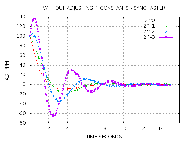
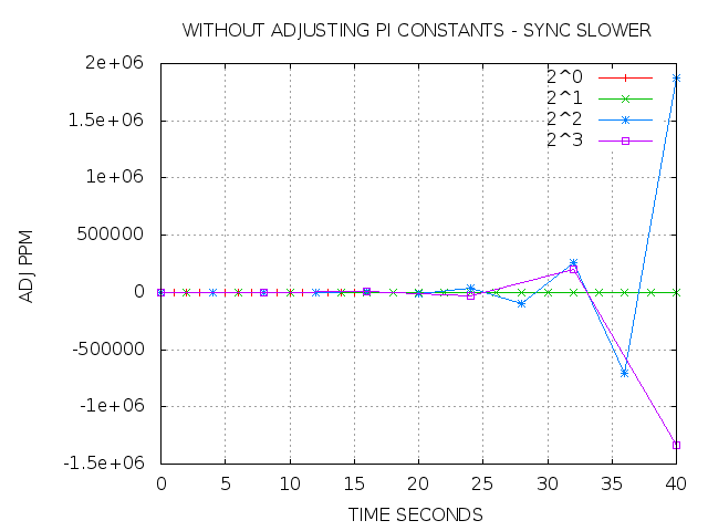
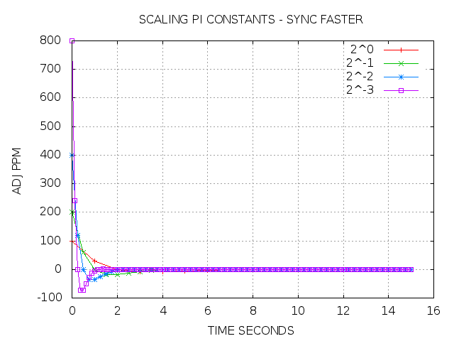
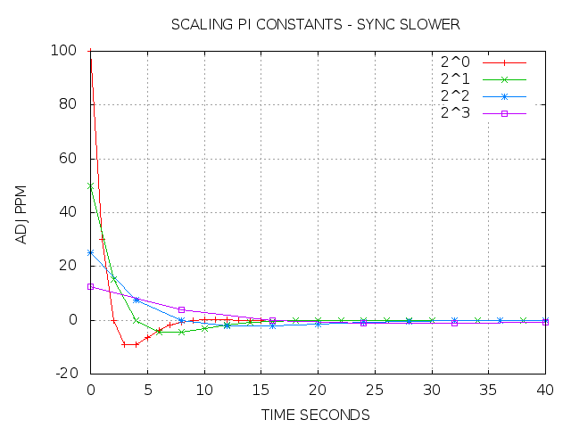
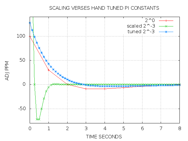
On Thu, Apr 25, 2013 at 01:08:13PM +0200, Miroslav Lichvar wrote: > On Wed, Apr 24, 2013 at 08:51:36PM +0200, Richard Cochran wrote: > > > Your simulation results are interesting. Do you propose to find PI > > values for different sync rates in this way? > > I think the simulations show that the constants can be scaled > proportionally with the update rate. I didn't expect that the constants may be scaled, and so a wrote a simulator of my own (not to be compared with clknetsim, of course). http://linuxptp.sourceforge.net/pi_const/ This program only simulates the PI controller with an ideal, noise-free error signal. By starting out with a time offset of 100 microseconds, the program plots the step response of the servo. First let us look at what linuxptp does today when the actual sync rate is faster than the default of 1 Hz. http://linuxptp.sourceforge.net/pi_const/plot1.png The x-axis is the simulation time, and the y-axis is the output of the servo in PPM. The red 2^0 line shows how the default constants cause the servo to settle within the expected 15 second interval. If we just use these same constants with an increased sync rate (2^ -1, -2, and -3), the the servo still converges in the same interval, but with over-steering. The faster the sync rate, the greater the overshooting. If the actual sync rate is slower than the default of 1 Hz, then the servo becomes unstable: http://linuxptp.sourceforge.net/pi_const/plot2.png So the current linuxptp behavior of applying constants tuned for a 1 Hz sync to other rates does not work very well, or not at all, unless the user provides constants tuned to the expected sync rate. Now let us consider scaling the constants to the sync rate. http://linuxptp.sourceforge.net/pi_const/plot3.png With rates over 1 Hz, the shape of convergence is improved, but you can still see the over-steering effect. For example, the 2^-3 case produces an initial 800 PPM adjustment for the 100 microsecond offset. When the sync rate is slower than 1 Hz, http://linuxptp.sourceforge.net/pi_const/plot4.png the result appears at first glance acceptable, but any noise in the error signal would probably spoil things. So my conclusion is that, although automatically scaling the constants is an improvement over blindly applying the defaults, still scaling is not the right solution. What we really want is a set of tuned PI constants, one for each combination of supported sync interval and HW/SW time stamping. As an example, compare the using the scaled defaults with using hand tuned constants for the 2^-3 sync interval. http://linuxptp.sourceforge.net/pi_const/plot5.png Thoughts? Thanks, Richard |
|
From: Miroslav L. <mli...@re...> - 2013-04-29 14:02:35
|
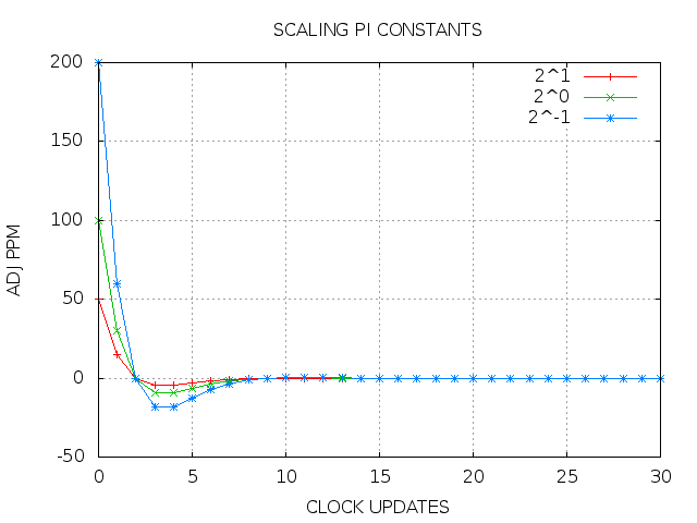
On Sat, Apr 27, 2013 at 09:15:39AM +0200, Richard Cochran wrote: > So the current linuxptp behavior of applying constants tuned for a 1 > Hz sync to other rates does not work very well, or not at all, unless > the user provides constants tuned to the expected sync rate. Agreed. > Now let us consider scaling the constants to the sync rate. > > http://linuxptp.sourceforge.net/pi_const/plot3.png > > With rates over 1 Hz, the shape of convergence is improved, but you > can still see the over-steering effect. The shape should be identical, just scaled differently. It can be seen better when the x axis is in clock updates instead of time. http://mlichvar.fedorapeople.org/tmp/pi_plot3x.png > For example, the 2^-3 case > produces an initial 800 PPM adjustment for the 100 microsecond offset. That's perfectly fine, the servo running at 8Hz rate is 8 times faster. The amount of offset corrected in one clock update is the same. > When the sync rate is slower than 1 Hz, > > http://linuxptp.sourceforge.net/pi_const/plot4.png > > the result appears at first glance acceptable, but any noise in the > error signal would probably spoil things. I think the jitter should have the same effect in the different rates. > So my conclusion is that, although automatically scaling the constants > is an improvement over blindly applying the defaults, still scaling is > not the right solution. It depends on what are our requirements. To ensure stable operation with different rates, the scaling is probably the easiest one to implement. Another could be clamping the constants to the value of rate in Hz. > What we really want is a set of tuned PI > constants, one for each combination of supported sync interval and > HW/SW time stamping. > > As an example, compare the using the scaled defaults with using hand > tuned constants for the 2^-3 sync interval. > > http://linuxptp.sourceforge.net/pi_const/plot5.png Do you want to adjust the constants with the rate so that the servo will work similarly well with the same jitter/wander ratio? That's what I was proposing originally, but I wanted it to be fully configurable instead of having only two presets for a "typical" system and SW/HW time stamping. I think we can select one configurable constant which will be independent from the update rate and calculate the rest from it. The constant could still have two default values for the SW and HW time stamping. It could be the P constant "normalized" for 1 Hz, the I constant "normalized" for 1 Hz, the Allan intercept, jitter divided by wander, or another arbitrary scale. The Allan intercept has an advantage over the others that it can be seen on the Allan deviation plot. Thanks, -- Miroslav Lichvar |
|
From: Richard C. <ric...@gm...> - 2013-04-30 17:11:48
|
On Mon, Apr 29, 2013 at 04:02:25PM +0200, Miroslav Lichvar wrote: > On Sat, Apr 27, 2013 at 09:15:39AM +0200, Richard Cochran wrote: > > > For example, the 2^-3 case > > produces an initial 800 PPM adjustment for the 100 microsecond offset. > > That's perfectly fine, the servo running at 8Hz rate is 8 times > faster. The amount of offset corrected in one clock update is the > same. No it is not perfectly fine. When approaching stopped traffic at a red right, some drivers step on the gas and then slam on the breaks at the last moment. If instead you ease off the gas, you still get the light at the same time, but the ride is much smoother. When we scale the 1 Hz constant for 8 Hz, for example, the servo first dials +800 PPM and then almost -100 PPM. Properly tuned constants don't do that, as you can see in the plot: > > http://linuxptp.sourceforge.net/pi_const/plot5.png > I think we can select one configurable constant which will be > independent from the update rate and calculate the rest from it. The > constant could still have two default values for the SW and HW > time stamping. It could be the P constant "normalized" for 1 Hz, the I > constant "normalized" for 1 Hz, the Allan intercept, jitter divided by > wander, or another arbitrary scale. The Allan intercept has an > advantage over the others that it can be seen on the Allan deviation > plot. I still don't understand what you are proposing. Given an intercept, how do you derive P and I? In any case, it is my understanding that the settling times and frequency responses are critical for the servo behavior. I guess I will have to refresh my control theory and see what I can come up with. Thanks, Richard |
|
From: Miroslav L. <mli...@re...> - 2013-04-30 19:29:39
|
On Tue, Apr 30, 2013 at 07:11:30PM +0200, Richard Cochran wrote: > When we scale the 1 Hz constant for 8 Hz, for example, the servo first > dials +800 PPM and then almost -100 PPM. Properly tuned constants > don't do that, as you can see in the plot: > > > > http://linuxptp.sourceforge.net/pi_const/plot5.png I'm not sure what I should see in the plot. The 2^0 and scaled 2^-3 curves are identical, just stretched differently. Why should be 100us offset corrected at 100 ppm good and at 800 ppm bad? Are you considering a situation with a typical wander? This is similar to the PLL and its time constant. Halving the time constant doubles the frequency adjustment. And the constant needs to be scaled with the update interval to not become unstable. > > I think we can select one configurable constant which will be > > independent from the update rate and calculate the rest from it. The > > constant could still have two default values for the SW and HW > > time stamping. It could be the P constant "normalized" for 1 Hz, the I > > constant "normalized" for 1 Hz, the Allan intercept, jitter divided by > > wander, or another arbitrary scale. The Allan intercept has an > > advantage over the others that it can be seen on the Allan deviation > > plot. > > I still don't understand what you are proposing. Given an intercept, > how do you derive P and I? I believe there is a formula to calculate P for given intercept and rate. Then the I constant can be calculated from P and the rate. The constants will need to be clamped to not become unstable (in that case a shorter update interval would give better results). I don't know the formulas, but I don't think it will be very difficult to figure them out from the simulations. I just didn't want to spend much time on it if you are opposed to the idea. Thanks, -- Miroslav Lichvar |
|
From: Richard C. <ric...@gm...> - 2013-05-01 05:52:21
|
On Tue, Apr 30, 2013 at 09:29:28PM +0200, Miroslav Lichvar wrote: > On Tue, Apr 30, 2013 at 07:11:30PM +0200, Richard Cochran wrote: > > > > > http://linuxptp.sourceforge.net/pi_const/plot5.png > > I'm not sure what I should see in the plot. The 2^0 and scaled 2^-3 > curves are identical, just stretched differently. Why should be 100us > offset corrected at 100 ppm good and at 800 ppm bad? Are you > considering a situation with a typical wander? When designing a controller, one of the factors is amount of steering. Minimizing the magnitude of the steering is a good thing. In the car example, it saves gas and wear on the brakes. For a clock, time based applications prefer small frequency errors to larger ones. In the plot, you can see that there are better choices of constants for different sample rates than just scaling. The hand tuned constants converge in the same time, but without inducing so much frequency error. Finding these constants requires some analysis. > I believe there is a formula to calculate P for given intercept and > rate. Then the I constant can be calculated from P and the rate. The > constants will need to be clamped to not become unstable (in that case > a shorter update interval would give better results). I don't know the > formulas, but I don't think it will be very difficult to figure them > out from the simulations. I just didn't want to spend much time on it > if you are opposed to the idea. Please go ahead and see what you come up with. I am interested to see how you do it and what the results are. The servo parameters involve trade offs, and so there is no one right answer. Even if the software ends up with a tabular approach (one PI pair per sync rate), still we can always include your results in table form. Thanks, Richard |
|
From: Miroslav L. <mli...@re...> - 2013-05-03 16:17:51
|
On Wed, May 01, 2013 at 07:52:03AM +0200, Richard Cochran wrote: > Please go ahead and see what you come up with. I am interested to see > how you do it and what the results are. The servo parameters involve > trade offs, and so there is no one right answer. Even if the software > ends up with a tabular approach (one PI pair per sync rate), still we > can always include your results in table form. I tried to find which PI constant give the best RMS time error in the simulation results when the jitter/wander ratio and update interval change and run lines through the points. I guess it could be done accurately by mathematical analysis, but that would be much more difficult, at least for me. Similarly, it should be possible to get constants which minimize the RMS frequency error or a combination of the two. Here is what I found, u is the update interval in seconds, a is the Allan intercept in seconds and jw is the jitter/wander ratio. The clamping constants were chosen so P+I ≈ 1/u and P*u ≈ (I*u)^0.5. jw ≈ (a / 2)^1.5 P_min_rms_time ≈ min(10^0.2 / (u^0.3 * jw^0.5), 0.62 / u) I_min_rms_time ≈ min(10^0.1 / (u^-0.4 * jw), 0.38 / u) Here are calculated constants for some selected Allan intercepts and update intervals. u\a | 1 | 10 | 100 | 1000 | 2^+4 | 3.9e-02 2.4e-02 | 3.9e-02 2.4e-02 | 3.7e-02 1.1e-02 | 6.5e-03 3.4e-04 | 2^+3 | 7.7e-02 4.8e-02 | 7.7e-02 4.8e-02 | 4.5e-02 8.2e-03 | 8.0e-03 2.6e-04 | 2^+2 | 1.5e-01 9.5e-02 | 1.5e-01 9.5e-02 | 5.6e-02 6.2e-03 | 9.9e-03 2.0e-04 | 2^+1 | 3.1e-01 1.9e-01 | 3.1e-01 1.5e-01 | 6.8e-02 4.7e-03 | 1.2e-02 1.5e-04 | 2^-0 | 6.2e-01 3.8e-01 | 4.7e-01 1.1e-01 | 8.4e-02 3.6e-03 | 1.5e-02 1.1e-04 | 2^-1 | 1.2e+00 7.6e-01 | 5.8e-01 8.5e-02 | 1.0e-01 2.7e-03 | 1.8e-02 8.5e-05 | 2^-2 | 2.5e+00 1.5e+00 | 7.2e-01 6.5e-02 | 1.3e-01 2.0e-03 | 2.3e-02 6.5e-05 | 2^-3 | 5.0e+00 1.5e+00 | 8.8e-01 4.9e-02 | 1.6e-01 1.5e-03 | 2.8e-02 4.9e-05 | 2^-4 | 6.1e+00 1.2e+00 | 1.1e+00 3.7e-02 | 1.9e-01 1.2e-03 | 3.4e-02 3.7e-05 | What do you think? -- Miroslav Lichvar |
|
From: Miroslav L. <mli...@re...> - 2013-06-28 08:51:13
|
On Wed, May 29, 2013 at 11:53:42AM +0200, Miroslav Lichvar wrote: > On Tue, May 28, 2013 at 07:16:15PM +0200, Richard Cochran wrote: > > # method B at 2^-4 > > # pi_proportional_const 3.2 > > # pi_integral_const 0.05 > > Hm, doesn't the method B give at 2^-4 kp=0.2 and ki=0.8? Well, it doesn't. It seems I was using a wrong formula for the method B the whole time. I had not noticed it was written with multiplication instead of division. The previous comparisons I made are invalid, I'm sorry. When I use the correct (hopefully) formula, the difference is much less dramatic. This comparison is with the original method A (with jw set correctly) vs the original method B (which doesn't have a jw parameter). u\jw | 1e0 | 1e1 | 1e2 | 1e3 | 2^-7 | -1 -2 | -4 -13 | -10 -23 | -14 -33 | 2^-6 | -2 -1 | -4 -11 | -8 -22 | -13 -31 | 2^-5 | -1 0 | -3 -10 | -8 -20 | -14 -30 | 2^-4 | -2 2 | -3 -9 | -8 -19 | -13 -29 | 2^-3 | -2 4 | -2 -8 | -7 -18 | -12 -28 | 2^-2 | -2 5 | -2 -7 | -7 -18 | -12 -28 | 2^-1 | -2 4 | -2 -6 | -7 -17 | -12 -27 | 2^+0 | -1 0 | -2 -5 | -7 -17 | -13 -28 | 2^+1 | 0 0 | -0 -1 | -6 -13 | -11 -24 | 2^+2 | 1 0 | 0 -1 | -3 -8 | -9 -20 | 2^+3 | 1 0 | 0 0 | -1 -3 | -6 -15 | 2^+4 | 0 0 | 1 0 | 0 -1 | -4 -10 | 2^+5 | 0 0 | 1 0 | 0 -0 | -1 -4 | 2^+6 | 0 0 | 1 0 | 1 0 | 0 -1 | 2^+7 | 1 0 | 0 0 | 1 0 | 0 -0 | Now, as I'm writing the patch for the extended servo configuration, I'm looking for some defaults I could put into it. The most imporant difference between the method A and B is in the exponents. If I set the scale and the limiting coefficients identically and in such a way that it gives the same defaults with 1 sec interval as the current HW time stamping default, this is what I get. method A': kp = min(0.7 * u^-0.3, 0.7/u) ki = min(0.3 * u^0.4, 0.3/u) method B': kp = min(0.7 * u^-0.5, 0.7/u) ki = min(0.3 * u^0.5, 0.3/u) u\jw | 1e0 | 1e1 | 1e2 | 1e3 | 2^-7 | -0 -8 | -3 -8 | -3 -8 | -2 -8 | 2^-6 | -0 -7 | -2 -7 | -2 -7 | -2 -7 | 2^-5 | 0 -6 | -2 -6 | -1 -6 | -1 -6 | 2^-4 | 0 -4 | -1 -5 | -1 -5 | -1 -5 | 2^-3 | 0 -3 | -1 -3 | -1 -3 | -1 -3 | 2^-2 | 1 -2 | -0 -2 | -0 -2 | -0 -2 | 2^-1 | 0 -1 | -0 -1 | -0 -1 | -0 -1 | 2^+0 | -0 -0 | -0 -0 | -0 -0 | -0 0 | 2^+1 | 0 0 | 0 -0 | 0 0 | 0 0 | 2^+2 | -0 -0 | 0 0 | -0 0 | -0 0 | 2^+3 | 0 -0 | -0 -0 | 0 0 | 0 0 | 2^+4 | -0 0 | -0 0 | 0 0 | 0 0 | 2^+5 | -0 -0 | 0 0 | -0 0 | 0 0 | 2^+6 | 0 0 | -0 0 | -0 -0 | -0 -0 | 2^+7 | -0 0 | -0 -0 | -0 -0 | -0 -0 | The difference is small, but it seems the -0.3 and 0.4 exponents are slighly better in minimizing both time error and frequency error. The limiting coefficients could be increased to allow more aggresive setting with longer intervals and reduce the error, but I think we can focus on that later. Thanks, -- Miroslav Lichvar |
|
From: Richard C. <ric...@gm...> - 2013-06-28 15:48:33
|
On Fri, Jun 28, 2013 at 10:51:02AM +0200, Miroslav Lichvar wrote: > On Wed, May 29, 2013 at 11:53:42AM +0200, Miroslav Lichvar wrote: > > On Tue, May 28, 2013 at 07:16:15PM +0200, Richard Cochran wrote: > > > # method B at 2^-4 > > > # pi_proportional_const 3.2 > > > # pi_integral_const 0.05 > > > > Hm, doesn't the method B give at 2^-4 kp=0.2 and ki=0.8? > > Well, it doesn't. It seems I was using a wrong formula for the method > B the whole time. I had not noticed it was written with multiplication > instead of division. The previous comparisons I made are invalid, I'm > sorry. That is quite alright, we will slowly get to a good result... I had meant to reply about the method B and also post a bunch of new measurements I made, but I just couldn't find the time. I will post them and also try out you new patch, hopefully soon. Thanks, Richard |
|
From: Miroslav L. <mli...@re...> - 2013-05-29 09:53:52
|
On Tue, May 28, 2013 at 07:16:15PM +0200, Richard Cochran wrote: > > First results are in: > > > > http://linuxptp.sourceforge.net/igb-master_bcc-slave_pps/ Very interesting, thank you for doing this. Is there any specification on the accuracy of the generated PPS signal and the accuracy of the PPS capture? Could be the PPS rate increased? I'd expect the jitter in the PPS offsets to be smaller than in the offsets measured by ptp4l, which doesn't seem happen here. An explanation for that could be that most of the error is the clock instability, i.e. the Allan intercept is extremely short. This could be on the master or the slave or both. Could you please try running the test again with a very short sync interval (-7?), free_running enabled and summary_interval set to the sync interval, so we can see the measured offsets and try to estimate the jitter and wander? > # method B at 2^-4 > # pi_proportional_const 3.2 > # pi_integral_const 0.05 Hm, doesn't the method B give at 2^-4 kp=0.2 and ki=0.8? Thanks, -- Miroslav Lichvar |
|
From: Richard C. <ric...@gm...> - 2013-05-28 17:16:38
|
On Tue, May 28, 2013 at 07:10:41PM +0200, Richard Cochran wrote: > On Thu, May 23, 2013 at 04:11:36PM +0200, Miroslav Lichvar wrote: > > On Wed, May 22, 2013 at 07:41:14PM +0200, Richard Cochran wrote: > > > Right, so after seeing your simulation results, I am going to try and > > > validate them using an actual PPS. > > > > Great, I'm looking forward to see your results. > > First results are in: > > http://linuxptp.sourceforge.net/igb-master_bcc-slave_pps/ And here is how the tests were conducted. The bcc was directly connected to the i210 by a short Ethernet cable. The script on the bcc (slave) looks like: testptp.m68k -f 0 testptp.m68k -s # NB: system time on the bcc starts at value zero testptp.m68k -e 600 & ptp4l.m68k -f config and the config file had the set of constants to try: # method A at 2^0 pi_proportional_const 0.47 pi_integral_const 0.11 # method B at 2^0 # pi_proportional_const 0.8 # pi_integral_const 0.2 # method A at 2^-4 # pi_proportional_const 1.1 # pi_integral_const 0.037 # method B at 2^-4 # pi_proportional_const 3.2 # pi_integral_const 0.05 Thanks, Richard |
|
From: Richard C. <ric...@gm...> - 2013-05-28 17:11:04
|
On Thu, May 23, 2013 at 04:11:36PM +0200, Miroslav Lichvar wrote: > On Wed, May 22, 2013 at 07:41:14PM +0200, Richard Cochran wrote: > > Right, so after seeing your simulation results, I am going to try and > > validate them using an actual PPS. > > Great, I'm looking forward to see your results. First results are in: http://linuxptp.sourceforge.net/igb-master_bcc-slave_pps/ - plot1.png Initial convergence at Sync 2^0 - plot2.png Initial convergence at Sync 2^-4 - plot3.png Steady state at Sync 2^0 - plot4.png Steady state at Sync 2^-4 For this test, I used the m5234bcc (phyter) as a slave to the Intel i210 card. The 1 PPS from the i210 was time stamped by the phyter. You can see a static offset of 400 nanoseconds, due to path asymmetry. Overall, method B is looking better, but that is just my impression, and I haven't really quantified that impression. I hope to repeat the test today, with the roles reversed. Thanks, Richard |
|
From: Richard C. <ric...@gm...> - 2013-05-10 17:21:01
|
On Fri, May 10, 2013 at 05:12:31PM +0200, Miroslav Lichvar wrote: > On Fri, May 10, 2013 at 10:41:13AM +0200, Richard Cochran wrote: > > I spent some time this week reviewing how to obtain good PI servo > > constants, and now I am even more convinced that the choice involves > > tradeoffs that only the end user can decide. > > What tradeoffs do you think the user can consider? For me, the only > things that matter are time error, frequency error and convergence > time. Yes, that pretty much says it all. > > 2. Should user constants appear in the config file, or should we have > > a new, separate file for that? > > How about a list of EXP:P:I triplets separated by commas in the config? I was thinking something more like: # Sync P I pi_constant 0 0.7 0.3 pi_constant -1 0.58 0.085 In that way, a config file can personalize as much or as little of the table as desired. Thanks, Richard |
|
From: Keller, J. E <jac...@in...> - 2013-05-10 18:16:42
|
> -----Original Message----- > From: Richard Cochran [mailto:ric...@gm...] > Sent: Friday, May 10, 2013 10:21 AM > To: Miroslav Lichvar > Cc: lin...@li... > Subject: Re: [Linuxptp-devel] Optimal P, I constants > > On Fri, May 10, 2013 at 05:12:31PM +0200, Miroslav Lichvar wrote: > > On Fri, May 10, 2013 at 10:41:13AM +0200, Richard Cochran wrote: > > > I spent some time this week reviewing how to obtain good PI servo > > > constants, and now I am even more convinced that the choice > involves > > > tradeoffs that only the end user can decide. > > > > What tradeoffs do you think the user can consider? For me, the only > > things that matter are time error, frequency error and convergence > > time. > > Yes, that pretty much says it all. > > > > 2. Should user constants appear in the config file, or should we have > > > a new, separate file for that? > > > > How about a list of EXP:P:I triplets separated by commas in the config? > > I was thinking something more like: > > # Sync P I > pi_constant 0 0.7 0.3 > pi_constant -1 0.58 0.085 > > In that way, a config file can personalize as much or as little of the > table as desired. > > Thanks, > Richard > I agree with that, and we can just comment out the ones we don't select, But if the user wants it is easy to just add the values they want. - Jake |
|
From: Miroslav L. <mli...@re...> - 2013-05-13 08:33:23
|
On Fri, May 10, 2013 at 07:20:42PM +0200, Richard Cochran wrote: > > > 2. Should user constants appear in the config file, or should we have > > > a new, separate file for that? > > > > How about a list of EXP:P:I triplets separated by commas in the config? > > I was thinking something more like: > > # Sync P I > pi_constant 0 0.7 0.3 > pi_constant -1 0.58 0.085 > > In that way, a config file can personalize as much or as little of the > table as desired. I'd rather avoid introducing a new config file and keep everything in the main config. There could be a new section for it. [pi_constants] #Sync P I 0 0.7 0.3 -1 0.52 0.085 Thanks, -- Miroslav Lichvar |
|
From: Keller, J. E <jac...@in...> - 2013-05-13 16:51:17
|
> -----Original Message----- > From: Miroslav Lichvar [mailto:mli...@re...] > Sent: Monday, May 13, 2013 1:33 AM > To: Richard Cochran > Cc: lin...@li... > Subject: Re: [Linuxptp-devel] Optimal P, I constants > > On Fri, May 10, 2013 at 07:20:42PM +0200, Richard Cochran wrote: > > > > 2. Should user constants appear in the config file, or should we > have > > > > a new, separate file for that? > > > > > > How about a list of EXP:P:I triplets separated by commas in the > config? > > > > I was thinking something more like: > > > > # Sync P I > > pi_constant 0 0.7 0.3 > > pi_constant -1 0.58 0.085 > > > > In that way, a config file can personalize as much or as little of the > > table as desired. > > I'd rather avoid introducing a new config file and keep everything in > the main config. There could be a new section for it. > I am pretty sure Richard didn't intend these to be in a new config file. > [pi_constants] > #Sync P I > 0 0.7 0.3 > -1 0.52 0.085 > > Thanks, > > -- > Miroslav Lichvar > I like using the headers, though it might make sense to stick to the same format we have everywhere else in the file for consistency. - Jake |
|
From: Miroslav L. <mli...@re...> - 2013-05-23 14:11:46
|
On Wed, May 22, 2013 at 07:41:14PM +0200, Richard Cochran wrote: > Right, so after seeing your simulation results, I am going to try and > validate them using an actual PPS. Great, I'm looking forward to see your results. > BTW, do you have a test setup to measure this yourself? If so, please > do tell us what you find. I don't have a setup to do that. Beside measuring the accuracy of the PTP clock, I'd like to be able to do it also with the system clock. I wish there was a way of getting the TSC as a pulse signal directly from the CPU. Thanks, -- Miroslav Lichvar |
|
From: Miroslav L. <mli...@re...> - 2013-05-10 15:12:42
|
On Fri, May 10, 2013 at 10:41:13AM +0200, Richard Cochran wrote: > I spent some time this week reviewing how to obtain good PI servo > constants, and now I am even more convinced that the choice involves > tradeoffs that only the end user can decide. What tradeoffs do you think the user can consider? For me, the only things that matter are time error, frequency error and convergence time. > I am going to introduce a table of constants, with one PI pair per > sync interval, but I have a few questions where I could use some > feedback. > > 1. What range of sync intervals should be supported? 2^-7 to 2^+7 ? I have no suggestion for that. > 2. Should user constants appear in the config file, or should we have > a new, separate file for that? How about a list of EXP:P:I triplets separated by commas in the config? Thanks, -- Miroslav Lichvar |
|
From: Richard C. <ric...@gm...> - 2013-05-22 17:41:32
|
On Wed, May 22, 2013 at 12:51:38PM +0200, Miroslav Lichvar wrote: > > It seems the cap plots are created from the RMS offsets reported by > ptp4l, which include the jitter. Even if the reported RMS offsets > are similar with both methods, the actual accuracy could be > significantly better with one method. Unfortunately that information > is hidden in the noise. To evaluate the accuracy of the clock > controlled by the servo, more accurate measurements are needed than > the measurements feeded to the servo. This is where simulations are > very useful. Right, so after seeing your simulation results, I am going to try and validate them using an actual PPS. BTW, do you have a test setup to measure this yourself? If so, please do tell us what you find. Thanks, Richard |