I recently got my Dust cover Flap device working again and wondered if it was possible to control LED lights via PWM instead of an EL panel? I use an external flat panel currently using modified arduino code for Alnitak LED driver. It uses an Arduino nano, a MOS circuit. A IRF520 MOSFET Driver Module (HCMODU0083) and a light panel, controlled via pin 3. I would like to control via the Darklight driver as it has the option for both opening a shutter and controlling the light. Currently I cannot see a way for the Alnitak driver to operate a flap. I think having an option between EL panel and LED driver would be a huge plus for this project. If there is a way to do it, can you please let me know.
/*What:LEDLightBoxAlnitak-PCcontrolledlightboximplmentedusingtheAlnitak(Flip-Flat/Flat-Man)commandsetfoundhere:http://www.optecinc.com/astronomy/pdf/Alnitak%20Astrosystems%20GenericCommandsR3.pdfWho:CreatedBy:JaredWellman-jared@mainsequencesoftware.comModifiedBy:RobertPascale-implementedthePWMcodefor31kHz-revertedfromtheV4protocolasitwasflaky.When:Lastmodified:2020/March/12Typicalusageonthecommandprompt:Send:>S000\n//requeststateRecieve:*S19000\n//returnedstateSend:>B128\n//setbrightness128Recieve:*B19128\n//confirmingbrightnesssetto128Send:>J000\n//getbrightnessRecieve:*B19128\n//brightnessvalueof128(assumingassetfromabove)Send:>L000\n//turnlighton(usessetbrightnessvalue)Recieve:*L19000\n//confirmslightturnedonSend:>D000\n//turnlightoff(brightnessvalueshouldnotbechanged)Recieve:*D19000\n//confirmslightturnedoff.*/volatileintledPin=3;//thepinthattheLEDisattachedto,needstobeaPWMpin.intbrightness=0;enumdevices{FLAT_MAN_L=10,FLAT_MAN_XL=15,FLAT_MAN=19,FLIP_FLAT=99};enummotorStatuses{STOPPED=0,RUNNING};enumlightStatuses{OFF=0,ON};enumshutterStatuses{UNKNOWN=0,//ienotopenorclosed...couldbemovingCLOSED,OPEN};intdeviceId=FLAT_MAN;intmotorStatus=STOPPED;intlightStatus=OFF;intcoverStatus=UNKNOWN;voidsetup(){//-----PWMfrequencyforD3&D11-----//Timer2divisor=2,16,64,128,512,2048TCCR2B=TCCR2B&B11111000|B00000001;//31KHz//TCCR2B=TCCR2B&B11111000|B00000010;//3.9KHz//TCCR2B=TCCR2B&B11111000|B00000011;//980Hz//TCCR2B=TCCR2B&B11111000|B00000100;//490Hz(default)//TCCR2B=TCCR2B&B11111000|B00000101;//245Hz//TCCR2B=TCCR2B&B11111000|B00000110;//122.5Hz//TCCR2B=TCCR2B&B11111000|B00000111;//30.6Hz//initializetheserialcommunication:Serial.begin(9600);//initializetheledPinasanoutput:pinMode(ledPin,OUTPUT);analogWrite(ledPin,0);}voidloop(){handleSerial();}voidhandleSerial(){if(Serial.available()>=6)//allincomingcommunicationsarefixedlengthat6bytesincludingthe\n{char*cmd;char*data;chartemp[10];intlen=0;charstr[20];memset(str,0,20);//Idon't personally like using the \n as a command character for reading.//butthat's how the command set is.Serial.readBytesUntil('\r',str,20);cmd=str+1;data=str+2;//usefulfordebuggingtomakesureyourcommandscamethroughandareparsedcorrectly.if(false){sprintf(temp,"cmd = >%c%s;",cmd,data);Serial.println(temp);}switch(*cmd){/*PingdeviceRequest:>P000\nReturn:*Pii000\nid=deviceId*/case'P':sprintf(temp,"*P%dOOO\n",deviceId);//MADECHANGEFROMPRINTLNTOPRINTHERESerial.print(temp);break;/*OpenshutterRequest:>O000\nReturn:*Oii000\nid=deviceIdThiscommandisonlysupportedontheFlip-Flat!*/case'O':sprintf(temp,"*O%dOOO\n",deviceId);//MADECHANGEFROMPRINTLNTOPRINTHERESetShutter(OPEN);Serial.print(temp);break;/*CloseshutterRequest:>C000\nReturn:*Cii000\nid=deviceIdThiscommandisonlysupportedontheFlip-Flat!*/case'C':sprintf(temp,"*C%dOOO\n",deviceId);//MADECHANGEFROMPRINTLNTOPRINTHERESetShutter(CLOSED);Serial.print(temp);break;/*TurnlightonRequest:>L000\nReturn:*Lii000\nid=deviceId*/case'L':sprintf(temp,"*L%dOOO\n",deviceId);//MADECHANGEFROMPRINTLNTOPRINTHERESerial.print(temp);lightStatus=ON;analogWrite(ledPin,brightness);break;/*TurnlightoffRequest:>D000\nReturn:*Dii000\nid=deviceId*/case'D':sprintf(temp,"*D%dOOO\n",deviceId);//MAKINGTESTCHANGEHEREWITHTHEREMOVALOFPRINTLNANDREPLACINGWITHJUSTTHENEWLINECHARACTERSerial.print(temp);lightStatus=OFF;analogWrite(ledPin,0);break;/*SetbrightnessRequest:>Bxxx\nxxx=brightnessvaluefrom000-255Return:*Biiyyy\nid=deviceIdyyy=valuethatbrightnesswassetfrom000-255*/case'B':brightness=atoi(data);if(lightStatus==ON)analogWrite(ledPin,brightness);sprintf(temp,"*B%d%03d\n",deviceId,brightness);//MADECHANGEFROMPRINTLNTOPRINTHERESerial.print(temp);break;/*GetbrightnessRequest:>J000\nReturn:*Jiiyyy\nid=deviceIdyyy=currentbrightnessvaluefrom000-255*/case'J':sprintf(temp,"*J%d%03d\n",deviceId,brightness);//MADECHANGEFROMPRINTLNTOPRINTHERESerial.print(temp);break;/*Getdevicestatus:Request:>S000\nReturn:*SidMLC\nid=deviceIdM=motorstatus(0stopped,1running)L=lightstatus(0off,1on)C=CoverStatus(0moving,1closed,2open)*/case'S':sprintf(temp,"*S%d%d%d%d\n",deviceId,motorStatus,lightStatus,coverStatus);//MADECHANGEFROMPRINTLNTOPRINTHERESerial.print(temp);break;/*GetfirmwareversionRequest:>V000\nReturn:*Vii001\nid=deviceId*/case'V'://getfirmwareversionsprintf(temp,"*V%d001\n",deviceId);//MADECHANGEFROMPRINTLNTOPRINTHERESerial.print(temp);break;}while(Serial.available()>0)Serial.read();}}voidSetShutter(intval){if(val==OPEN&&coverStatus!=OPEN){coverStatus=OPEN;//TODO:ImplementcodetoOPENtheshutter.}elseif(val==CLOSED&&coverStatus!=CLOSED){coverStatus=CLOSED;//TODO:ImplementcodetoCLOSEtheshutter}else{//TODO:ActuallyhandlethiscasecoverStatus=val;}}
If you would like to refer to this comment somewhere else in this project, copy and paste the following link:
Ok had a look at the code a little closer, it seems the EL panel PWM is adjusted via pin 3, the same as the Alnitak code. So my assumption would be that the Darklight Controller along with a MOS driver, the controller should be able to operate it. I will be testing this thory this week. If so this will make this project so much easier for me to use. :)
If you would like to refer to this comment somewhere else in this project, copy and paste the following link:
Thank you for your question. It's possible to control LEDs instead of an EL Panel. My design has a maximum voltage output of 12V to the light source; you need to find LEDs that support this voltage or add some components to reduce it.
R/
Nathan
If you would like to refer to this comment somewhere else in this project, copy and paste the following link:
Hello, i am sorry if this is not the right thrrad to ask my question.
i have followed instructions, soldered everything togather. When i connect arduino via usb to my pc i am able to upload the sketch to it but when i try to use the cover/panel via app nothing works, nothing is happening. Now i will admit, i did not cut my usb cable, i did not see enough images nor explanations about that and i figured i already have usb cable from my arduino to pc. now that might be where issue lies, i dont know. i hope to get some help.
thank you.
If you would like to refer to this comment somewhere else in this project, copy and paste the following link:
Hi Peter,
I'm sorry to hear you've hit a snag in your development.
It's OK not to cut the USB cable if you can connect directly to your Arduino. The purpose of a larger USB cable was to maintain comparable sizing to other equipment. The instructions for cutting the cable and the pinout can be found on page 12 of the manual.
Regarding your setback, unfortunately, you don't provide many details, so it's hard to offer advice at this time. When you say you "try to use the cover/panel via app nothing works, nothing is happening," what do you mean? Are you able to successfully connect to the Arduino? If you're connected, what are you seeing for the status of the panel position and state of the light? Are they connected to the Arduino? Please provide more details; I'll be more than happy to try and assist.
R/
Nathan
If you would like to refer to this comment somewhere else in this project, copy and paste the following link:
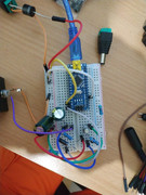
Thank you for replying. You are correct, i did not provide much details. Here are the images of my board. I switched arduino position because i wanted to be able to plug usb directly inside the box. When i connect only 12v power, arduino does not light up, it only lights up when i ppug it into the pc. When i connect usb to pc, EL panel to the appropriate cable and servo motor to its plug and open the app, i am able to connect the app to the device, or so i think because there is no error message when i do connect it. When i click on the open button/close button app shows how status has changed, same for the light, but nothing happens, servo does not move, EL panel does not light up. I am not sure if i have connected NPN and PNP correctly.
Id be willing to answer any additional question in order to solve this issue i am having.
Hi, Peter; thanks for the additional information and the picture. You definitely have a power issue because, at minimum, without the USB connected, the Arduino should be getting power, and it would also explain why neither the EL panel doesn't light up nor the servo move. Could you provide a picture of the bottom of your circuit board so I can attempt to trace all of your connections? Also, what is the rating of your power supply?
R/
Nathan
If you would like to refer to this comment somewhere else in this project, copy and paste the following link:
Makes sense. In all previous projects, arduino would light up when power is connected even though it has not been plugged into pc.
is the first big diode connected in the right direction?
Looking at the two images and solving why there is no power going to the Arduino first, the circuit seems correct. What is the power supply you are using? 12V # Amps? Do you have a voltmeter? Unplug the USB before starting, and let's walk through the components. Check the voltage at the beginning before the first diode. Are you getting a reading? What is it? Keep the ground lead on the input ground; are you getting a voltage after the first diode? After the first resistor, tied to the Zener diode, are you also getting a voltage? What is it?
If you would like to refer to this comment somewhere else in this project, copy and paste the following link:
I have managed to get the servo motor to work. LM1084IT-ADJ was wired wrong. NPN transistor was also wired wrong and i hoped that would solve my problems but nope. Still cant get EL panel to light up. I checked the wires leading from the board and they are live, all the time but EL panel doesnt want to light up. I am missing something here. i checked the EL panel itself by wiring it back to its little (buzzing while turned on) power transformer which came with the EL panel.
I dont know if EL panel is suppose to work without that little box, hooked directly with two lead wired onto the board?
If you would like to refer to this comment somewhere else in this project, copy and paste the following link:
Peter,
I'm glad you've gotten it partially resolved. The EL Panel will not work if connected directly to the board. You need the little box; it's an inverter and converts from DC to AC. If it still doesn't work after that, check the PNP and verify it is connected correctly. If that still doesn't work, I'd recommend changing the NPN and/or the PNP; one or both may have gone bad if it was initially wired incorrectly. I've done that myself a time or two. Let me know the results, and we'll go from there.
Last edit: Nathan Woelfle 2023-11-05
If you would like to refer to this comment somewhere else in this project, copy and paste the following link:
Hey Nathan, i have not been able to resolve it yet. I did not know that i wouod need that small box DC-AC converter as well in the mix.
So ive looked at the schematics in the manual and from what ive gathered while watching youtube videos on NPN and PNP, it seems that you have switched them up or at least labled them up wrongly in the image of your board, where you have servo and EL panel electronics devided by the color.
First NPN should be closer to the EL panel plug. I did that. ive switched PNP and NPN like your schematics shows but still no luck.
I checked exit power plug for EL panel which should go to little box. it has 11.5v of power all the time regardless of whether i have panel turned on or off in the app.
Maybe the issue is so easy but i am just missing it.
Peter,
You are correct; I did mislabel the two transistors in the image. Great catch, thank you! I will have to update. The schematic, though, is correct and should be what it followed.
If you've installed the transistors correctly, as shown in the schematic, which is correct, then one or both transistors may have been damaged or are faulty. Here's a video for how to check them to make sure they are both functioning correctly. https://youtu.be/93bO2nBrptM?feature=shared
Let me know the results.
R/
Nathan
If you would like to refer to this comment somewhere else in this project, copy and paste the following link:
Yeah, i did everything according to schematics with brand new components -no luck.
ive recreated just the flat panel portion on protoboard.
Still wont turn EL panel on.
i have power at the little box for the EL panel regardless of what app is saying whether its on or off...
If you would like to refer to this comment somewhere else in this project, copy and paste the following link:
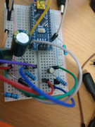
Peter,
Thanks for posting the pictures. Everything appears connected correctly, so it's odd that it isn't working for you. Please provide the model #s for the two transistors you're using so I can doublecheck the pinout to be more confident, though.
I want to clarify a couple of things. When you say you "have power at the little box," is what looks like the audio jack on the left side of the image, is the little box you're referring to? Is that the inverter? What voltage are you getting, and at which point in the circuit are you measuring? If you don't have the inverter physically connected or something to provide a load, like a resistor, when you initially check the voltage, if, at the audio jack, it most likely would read ~12V. The capacitors will charge up and show a voltage, which may slowly drain when a voltmeter is connected.
I also understand when you say the EL panel won't turn on even though you're getting a voltage at the little box. Have you directly connected the inverter up to 12V and verified the EL Panel does come on? Do you have a make/model for those parts that you can provide?
I'm very intrigued by the situation and sorry for the frustration and time it's taking for us to get this resolved, but I look forward to tracking down our issue.
If you would like to refer to this comment somewhere else in this project, copy and paste the following link:
Okay, electronics do work.
i was blindly following the image of the board, rather than schematics. My PNP and NPN were not placed correctly but now it finally works.
At first i was quite worried that EL panel was way too dim but after testing it, its working quite well.
Next part is to print out the EL panel holder/cover for my 150P Newtonian.
This is such a nice project and huge thanks to the maker Nathan who has been quite helpful and active in quick replies. Without him i would be stuck hehe.
Thank you and i hope everyone makes this for their own telescope.
If you would like to refer to this comment somewhere else in this project, copy and paste the following link:
Awesome Peter! I'm glad you got it working. Thank you for the kind words. It was my pleasure to be able to assist. I hope to see pictures of your build and future photos here or on one of the web forums.
If you would like to refer to this comment somewhere else in this project, copy and paste the following link:
HI Nathan and all,
I recently got my Dust cover Flap device working again and wondered if it was possible to control LED lights via PWM instead of an EL panel? I use an external flat panel currently using modified arduino code for Alnitak LED driver. It uses an Arduino nano, a MOS circuit. A IRF520 MOSFET Driver Module (HCMODU0083) and a light panel, controlled via pin 3. I would like to control via the Darklight driver as it has the option for both opening a shutter and controlling the light. Currently I cannot see a way for the Alnitak driver to operate a flap. I think having an option between EL panel and LED driver would be a huge plus for this project. If there is a way to do it, can you please let me know.
Regards,
Andrew Wall
South Australia.
http://brightskyobservatory.bsch.com.au/
The current code I am using is this one below.
Ok had a look at the code a little closer, it seems the EL panel PWM is adjusted via pin 3, the same as the Alnitak code. So my assumption would be that the Darklight Controller along with a MOS driver, the controller should be able to operate it. I will be testing this thory this week. If so this will make this project so much easier for me to use. :)
Hi Andrew,
Thank you for your question. It's possible to control LEDs instead of an EL Panel. My design has a maximum voltage output of 12V to the light source; you need to find LEDs that support this voltage or add some components to reduce it.
R/
Nathan
Hello, i am sorry if this is not the right thrrad to ask my question.
i have followed instructions, soldered everything togather. When i connect arduino via usb to my pc i am able to upload the sketch to it but when i try to use the cover/panel via app nothing works, nothing is happening. Now i will admit, i did not cut my usb cable, i did not see enough images nor explanations about that and i figured i already have usb cable from my arduino to pc. now that might be where issue lies, i dont know. i hope to get some help.
thank you.
Hi Peter,
I'm sorry to hear you've hit a snag in your development.
It's OK not to cut the USB cable if you can connect directly to your Arduino. The purpose of a larger USB cable was to maintain comparable sizing to other equipment. The instructions for cutting the cable and the pinout can be found on page 12 of the manual.
Regarding your setback, unfortunately, you don't provide many details, so it's hard to offer advice at this time. When you say you "try to use the cover/panel via app nothing works, nothing is happening," what do you mean? Are you able to successfully connect to the Arduino? If you're connected, what are you seeing for the status of the panel position and state of the light? Are they connected to the Arduino? Please provide more details; I'll be more than happy to try and assist.
R/
Nathan
Thank you for replying. You are correct, i did not provide much details. Here are the images of my board. I switched arduino position because i wanted to be able to plug usb directly inside the box. When i connect only 12v power, arduino does not light up, it only lights up when i ppug it into the pc. When i connect usb to pc, EL panel to the appropriate cable and servo motor to its plug and open the app, i am able to connect the app to the device, or so i think because there is no error message when i do connect it. When i click on the open button/close button app shows how status has changed, same for the light, but nothing happens, servo does not move, EL panel does not light up. I am not sure if i have connected NPN and PNP correctly.
Id be willing to answer any additional question in order to solve this issue i am having.
Hi, Peter; thanks for the additional information and the picture. You definitely have a power issue because, at minimum, without the USB connected, the Arduino should be getting power, and it would also explain why neither the EL panel doesn't light up nor the servo move. Could you provide a picture of the bottom of your circuit board so I can attempt to trace all of your connections? Also, what is the rating of your power supply?
R/
Nathan
Makes sense. In all previous projects, arduino would light up when power is connected even though it has not been plugged into pc.
is the first big diode connected in the right direction?
The first big diode is in the right direction.
Looking at the two images and solving why there is no power going to the Arduino first, the circuit seems correct. What is the power supply you are using? 12V # Amps? Do you have a voltmeter? Unplug the USB before starting, and let's walk through the components. Check the voltage at the beginning before the first diode. Are you getting a reading? What is it? Keep the ground lead on the input ground; are you getting a voltage after the first diode? After the first resistor, tied to the Zener diode, are you also getting a voltage? What is it?
I have managed to get the servo motor to work. LM1084IT-ADJ was wired wrong. NPN transistor was also wired wrong and i hoped that would solve my problems but nope. Still cant get EL panel to light up. I checked the wires leading from the board and they are live, all the time but EL panel doesnt want to light up. I am missing something here. i checked the EL panel itself by wiring it back to its little (buzzing while turned on) power transformer which came with the EL panel.
I dont know if EL panel is suppose to work without that little box, hooked directly with two lead wired onto the board?
Peter,
I'm glad you've gotten it partially resolved. The EL Panel will not work if connected directly to the board. You need the little box; it's an inverter and converts from DC to AC. If it still doesn't work after that, check the PNP and verify it is connected correctly. If that still doesn't work, I'd recommend changing the NPN and/or the PNP; one or both may have gone bad if it was initially wired incorrectly. I've done that myself a time or two. Let me know the results, and we'll go from there.
Last edit: Nathan Woelfle 2023-11-05
Hey Nathan, i have not been able to resolve it yet. I did not know that i wouod need that small box DC-AC converter as well in the mix.
So ive looked at the schematics in the manual and from what ive gathered while watching youtube videos on NPN and PNP, it seems that you have switched them up or at least labled them up wrongly in the image of your board, where you have servo and EL panel electronics devided by the color.
First NPN should be closer to the EL panel plug. I did that. ive switched PNP and NPN like your schematics shows but still no luck.
I checked exit power plug for EL panel which should go to little box. it has 11.5v of power all the time regardless of whether i have panel turned on or off in the app.
Maybe the issue is so easy but i am just missing it.
Peter,
You are correct; I did mislabel the two transistors in the image. Great catch, thank you! I will have to update. The schematic, though, is correct and should be what it followed.
If you've installed the transistors correctly, as shown in the schematic, which is correct, then one or both transistors may have been damaged or are faulty. Here's a video for how to check them to make sure they are both functioning correctly. https://youtu.be/93bO2nBrptM?feature=shared
Let me know the results.
R/
Nathan
Yeah, i did everything according to schematics with brand new components -no luck.
ive recreated just the flat panel portion on protoboard.
Still wont turn EL panel on.
i have power at the little box for the EL panel regardless of what app is saying whether its on or off...
Peter,
Thanks for posting the pictures. Everything appears connected correctly, so it's odd that it isn't working for you. Please provide the model #s for the two transistors you're using so I can doublecheck the pinout to be more confident, though.
I want to clarify a couple of things. When you say you "have power at the little box," is what looks like the audio jack on the left side of the image, is the little box you're referring to? Is that the inverter? What voltage are you getting, and at which point in the circuit are you measuring? If you don't have the inverter physically connected or something to provide a load, like a resistor, when you initially check the voltage, if, at the audio jack, it most likely would read ~12V. The capacitors will charge up and show a voltage, which may slowly drain when a voltmeter is connected.
I also understand when you say the EL panel won't turn on even though you're getting a voltage at the little box. Have you directly connected the inverter up to 12V and verified the EL Panel does come on? Do you have a make/model for those parts that you can provide?
I'm very intrigued by the situation and sorry for the frustration and time it's taking for us to get this resolved, but I look forward to tracking down our issue.
Okay, electronics do work.
i was blindly following the image of the board, rather than schematics. My PNP and NPN were not placed correctly but now it finally works.
At first i was quite worried that EL panel was way too dim but after testing it, its working quite well.
Next part is to print out the EL panel holder/cover for my 150P Newtonian.
This is such a nice project and huge thanks to the maker Nathan who has been quite helpful and active in quick replies. Without him i would be stuck hehe.
Thank you and i hope everyone makes this for their own telescope.
Awesome Peter! I'm glad you got it working. Thank you for the kind words. It was my pleasure to be able to assist. I hope to see pictures of your build and future photos here or on one of the web forums.