Menu
▾
▴
Useage
Anonymous
This information only applies to versions of the library prior to Beta 1.0
Hardware Connections
Arduino connections:
- pin8 must be connected to video
- Will change to pin 7!!! already has in pre-release svn
- pin9 must be connected to sync. Hard coded Not changable
Arduino Mega connection: - pin11 must be connected to sync
- pin12 must be connected to video
- Will change!!!
Changing the Resolution
Version [r4] and up
Resolution changes may be done as follows: TV.begin(mode,hres,vres); There are limits to this see the description of begin(mode,hres,vres).
Versions up to and including [r3]
[r3] should be used for slightly more user execution time, slightly less memory usage, and much smaller flash usage, otherwise use the latest version.
Open up video_properties.h and change the lines:
-
define _RESOLUTION_HORIZONTAL 128 _
-
define RESOLUTION_VERTICAL 96
To the desired resolution. There are a few restrictions to this however: - _RESOLUTION_HORIZONTAL must be set to a multiple of 8. _
(_RESOLUTION_HORIZONTAL/8)*_RESOLUTION_VERTICALmust be smaller than the amount of SRAM the Arduino has, It also must leave some memory for the user applications and the library to run.- 160 is currently the maximum supported resolution, Higher is possible but it will require the use of a whole port rather than pin. EX: the analog pins may be all used to output video, but none could be used for any other output.
- In the future I do plan to implement an easer way to change the resolution.
Description of what each method does:
- begin(mode)
- Clears the screen and starts generating video @ 128x96
- mode:
- _PAL: selects PAL output _
- NTSC: selects NTSC output
- Returns(char):
- 0: if the function completed correctly.
- 4: if there is not enough memory for the resolution.
- begin(mode,hres,vres)
- Clears the screen and starts generating video
- mode:
- _PAL: selects PAL output _
- NTSC: selects NTSC output
- hres:
- Horizontal resolution to output must be divisible by 8 and be with the range of 104-152
- pre-release svn using a standard arduino(needs quick video pin change for sanguino/mega) the upper limit is now 240 pixels.
- vres:
- Vertical resolution
- PAL vres <= 260
- NTSC vres <= 216
- Returns(char):
- 0: if the function completed correctly.
- 1: if hres was not divisible by 8
- 2: if hres was to large to render(hardware limit)
- 3: if vres is to large for selected mode
- 4: if there is not enough memory for the resolution
- 5: if hres is not a supported resolution(software limit)
- pause()
- Will pause Rendering of video giving back full cpu time.
- Sync pulses will continue to be generated by the hardware.
- resume()
- Restarts the rendering process.
- clear_screen()
- sets the screen to be completely black.
- This is a macro: fill(0)
- invert()
- Inverts the color of the whole screen.
- This is a macro: fill(2)
- fill(color)
- color:
- 0: BLACK
- 1: WHITE
- 2: INVERT
- hres()
- Returns the Horizontal resolution as an unsigned char.
- vres()
- Returns the Vertical resolution as an unsigned char.
- char_line()
- returns the number of printable characters per line as a char.
- delay(x)
- delay an x number of frames.
- NTSC: An x of 60 gives 1 second of delay.
- PAL: An x of 50 gives 1 second of delay.
- set_pixel(x,y,c)
- sets a pixel at (x,y)
- c determines what color the point is set to.
- c=0 BLACK
- c=1 WHITE
- c=2 INVERT
- get_pixel(x,y)
- Gets the color of a pixel, returns an unsigned char.
- return=0 BLACK
- return=1 WHITE
- draw_line(x0,y0,x1,y1,c)
- Draw a line from (x0,y0) to (x1,y1)
- c determines what color the line is set to.
- c=0 black
- c=1 white
- c=2 invert color of this pixel
- draw_box(x0,y0,x1,y1,c,d,e,f)
- See the source this is going to change
- Will be split into:
- draw_rbox() for a rounded rectangle
- draw_box() for a regular rectangle
- draw_circle(x0,y0,radius,c,d,h)
- See the source this is going to change
- fs_bitmap()
- Draws a bitmap defined in the library to be expanded on...
- select_font(f)
- f:
- _3X5: 3x5 font really a 4x6 _
- 5X7: 5x7 font really a 6x8 default selection.
- _8X8: 8x8 font _
- print_char(x,y,c)
- Print the character c at (x,y)
- print_str(x,y,str)
- Print the null terminated string str at (x,y)
The following macros exist to maintain compatibility with earlier versions of the library:
- The macro.
- What it evaluates to.
- start_render(mode)
- begin(mode)
- pause_render()
- pause()
- resume_render()
- resume()
- horz_res()
- hres()
- vert_res()
- vres()
- delay_frame(x)
- delay(x)

View and moderate all "wiki Discussion" comments posted by this user
Mark all as spam, and block user from posting to "Wiki"
Originally posted by: rice103
but color? isn't there the pwm OUT?
View and moderate all "wiki Discussion" comments posted by this user
Mark all as spam, and block user from posting to "Wiki"
Originally posted by: figley.m...@gmail.com
DawsDesign?, i do not know about 675 Ohm, but if you have two 675 Ohm resistors, connect it in parallel and use instead of 330 Ohm, so you will have 675 / 2 = 337,5.
View and moderate all "wiki Discussion" comments posted by this user
Mark all as spam, and block user from posting to "Wiki"
Originally posted by: DawsDes...@gmail.com
Ok, I broke down and bought 330 and 1k resistors. I hooked everything up, put the NTSC sample sketch on my arduino, changed the TV.start_render to TV.begin (I'm using a 168) changed my TV's input to FRONT and booted up the arduino. Nothing. Blue screen. Tested my Playstation 2 on that video in and it worked. Does this only work on certain TVs? I tried a battery power source as well as USB power and I tried with and without diodes.
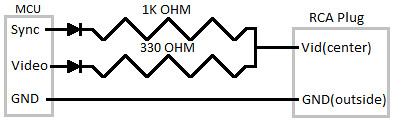
My schema goes like this:
PIN9->Diode->1k Resistor ->RCA Tip
PIN8->Diode->330 Resistor ->RCA Tip
GND->RCA Outside
Here's a crappy? pic: http://imgur.com/5fWi0
View and moderate all "wiki Discussion" comments posted by this user
Mark all as spam, and block user from posting to "Wiki"
Originally posted by: mdmetzle@gmail.com
Try TV.begin(MODE,104,48) were MODE is either _NTSC or _PAL The 168 does not have enough memory for the default resolution. also make sure the diodes are oriented correctly.
Also no this does not work on all tvs however if it doesn't work on your tv it will be jittery not no signal.
View and moderate all "wiki Discussion" comments posted by this user
Mark all as spam, and block user from posting to "Wiki"
Originally posted by: pewpew...@gmail.com
DawsDesign?, i used up changable 10k resistor R1212N-A10K-L20KC.

and, guys... using extended ascii in 8x8 font (i mean 128-255) needs to use unsigned char instead of signed.
View and moderate all "wiki Discussion" comments posted by this user
Mark all as spam, and block user from posting to "Wiki"
Originally posted by: n68...@yahoo.com
It's probably your setup with the RCA cable. The signal voltages are so low 0-1v that a dodgy connection anywhere will cause a fail (main reason for most digital ICs running at 5v.) I had the same problem with my first TVout project and was scratching my head for 2 weeks. After messing with it for the last time, (I was about fed up enough to throw something,) I turned around and went to work on my computer for about 45min. After cooling off a bit, I tried again. I moved the RCA jack from one tv to another and all of a sudden it worked. Moved it back and the other tv was suddenly working too. Had no Idea why it started working all of a sudden and was almost as mad about it working after me not changing a thing as I had been about it not working.
Took another 2 days to figure out that it was the cheap RCA jack I had soldered leads to and then plugged into my bread board. After my discovery I just fiddled with the connection between the RCA jack and the RCA cable whenever I got no signal. Eventually it stopped working all together but at least by then I knew how to fix it.
Get a good RCA jack (mine wasn't grabbing the center pin of the cable hard enough) and solder good leads to it. An upgrade from a 25cent junky RCA jack to a $2.00 gold plated jack did the trick for me (I would have gone for mid grade but the local radio shack was all out of $1.15 jacks. I shouldn't have been so hesitant to spend the extra 85cents.) RF signals are finicky and attention to detail and a bit of overkill can pay dividends when working with it. The shortcut method of cutting a cable open and using alligator clips may have been what did you in. Try playing with the RF connections (anything with a tv signal running through it,) you should get a reaction of some sort from the TV, if not an actual image. If you still don't get anything, try redoing the RF section of your circuit (the bread board to RCA interface specifically.) These things can be incredibly frustrating, especially when it turns out to be the result of a perfectly reasonable attempt at saving a dollar.
View and moderate all "wiki Discussion" comments posted by this user
Mark all as spam, and block user from posting to "Wiki"
Originally posted by: nhg.mani...@googlemail.com
i set it all up like this, and run the demo, but i always get a black screen. i get a signal, but this signal is black screen.(i know that there is a signal because if there were no signal, the tv would say "no signal") can anyone help me?
View and moderate all "wiki Discussion" comments posted by this user
Mark all as spam, and block user from posting to "Wiki"
Originally posted by: mdmetzle@gmail.com
Are you using the 1.0 beta? if so then the problem is the pinout changed. Ignore this page for the beta, the rest of the wiki contains the new setup and use informatiion
View and moderate all "wiki Discussion" comments posted by this user
Mark all as spam, and block user from posting to "Wiki"
Originally posted by: infi...@gmail.com
Hello,
My hardware setup is Atmega328 running at 8mhz (with output at PB3,PB4,PB5). I changed the pins defined in the harware_setup.h file respectively but cant get any output. Also I have observed that most of the TV PAL signal examples work on the PB0 and PB1 only if I change it to other PINS or other ports I don't get any output.I have been trying to get the TVout working for a week now. I have even tried to get it run on 168 running at 16Mhz but I cant get any output. I am on PAL.
Kindly let me know how do I change the code to get the TVOUT running on atmega328 at 8mhz with sync and vid on PB3 and PB4. And the same for Atmega168 at 16 Mhz on PB0 and PB1.
View and moderate all "wiki Discussion" comments posted by this user
Mark all as spam, and block user from posting to "Wiki"
Originally posted by: tobocl...@hotmail.com
great library, nor have pity that not even see color tones in the colors through the port pwm.
View and moderate all "wiki Discussion" comments posted by this user
Mark all as spam, and block user from posting to "Wiki"
Originally posted by: phongpha...@gmail.com
i have a problem with TV out it say 'TVout' does not name a type
View and moderate all "wiki Discussion" comments posted by this user
Mark all as spam, and block user from posting to "Wiki"
Originally posted by: jtmc...@gmail.com
I have the same problem with mine. The main reason I came here was to learn how to fix it.
View and moderate all "wiki Discussion" comments posted by this user
Mark all as spam, and block user from posting to "Wiki"
Originally posted by: WB7ODYF...@yahoo.com
http://www.instructables.com/id/TV-Out-with-Arduino/ Here is where I uploaded some modified test code that works with Arduino Uno R3 Plus. I gave instructions and many links to help the next guy. I even got the audio out pin to work, too. Used a 1K and 470 Ohm resistor Series ladder to connect to the Red Audio input connector on the back of the TV. Fred Finster Good luck to you. Give it a try, this was a simple project. I might display temperature from a DS 18B20 sensor on the TV. Audio beep if temperature is out of range to notify user.
View and moderate all "wiki Discussion" comments posted by this user
Mark all as spam, and block user from posting to "Wiki"
Originally posted by: pistoler...@gmail.com
Absolutely great library!!
Just for everybody to know, I successfully overlayed video NTSC and PAL using 208x208 pixels using this library with arduino mega R3, seeeduino mega R3 along with a LM1881N IC.
Now I want to make this library available for arduino DUE but I need to learn some stuff first, like how the render is done and how the timers and interrupts are handled in the new uC.
Does anybody know if it's already done?
Thanks for this awesome library!!!